[0007]It is accordingly an object of the invention to provide a method for fabricating a patterned layer on a semiconductor substrate that overcomes the above-mentioned disadvantages of the prior art methods of this general type, in which resist degradations can be avoided in a simple manner.
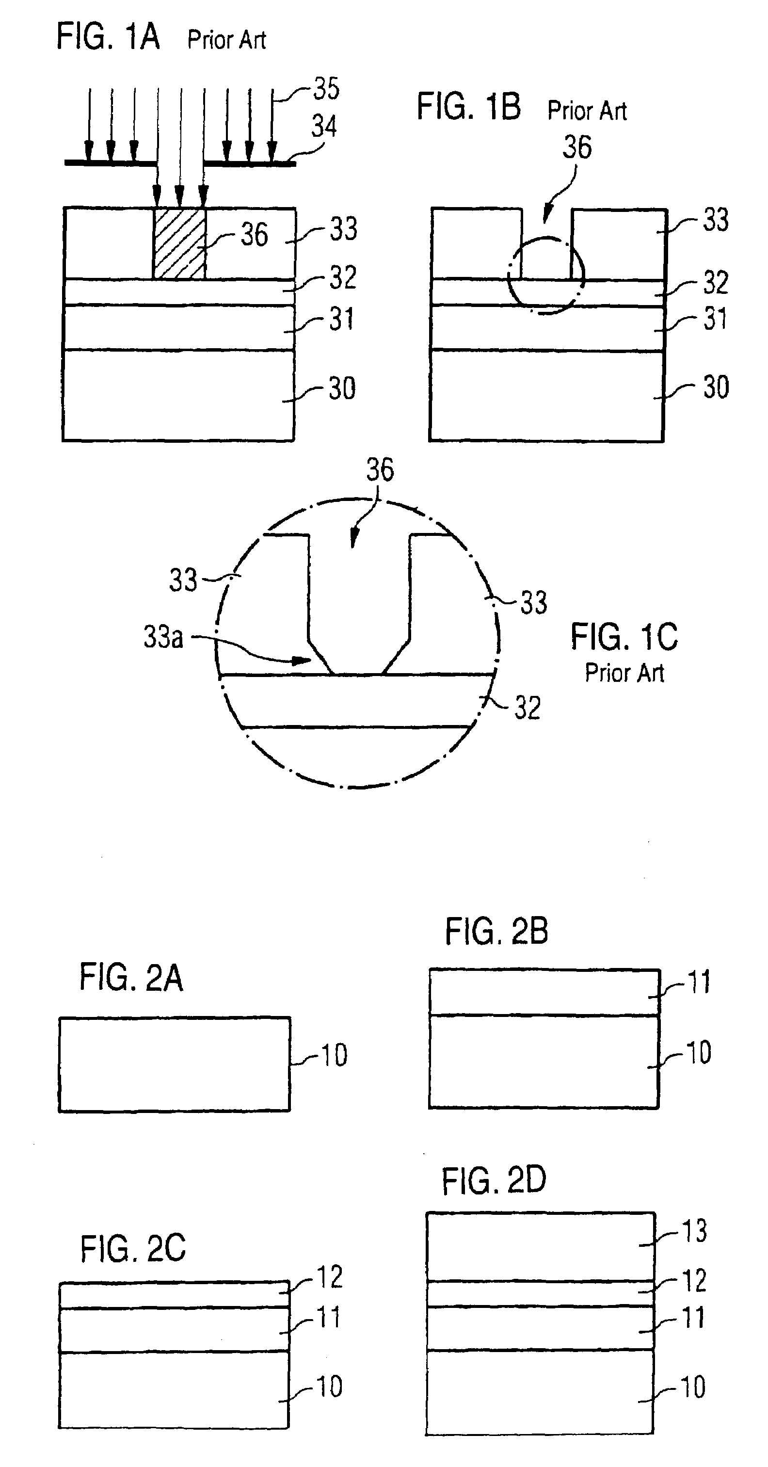
[0009]According to the invention, in order to fabricate the patterned layer on the semiconductor substrate, after the production of the N-containing
dielectric antireflection layer on the layer to be patterned, the N-free SiOx layer is deposited and only then is the photoresist layer produced thereon. The N-free SiOx layer produces a
nitrogen barrier for the
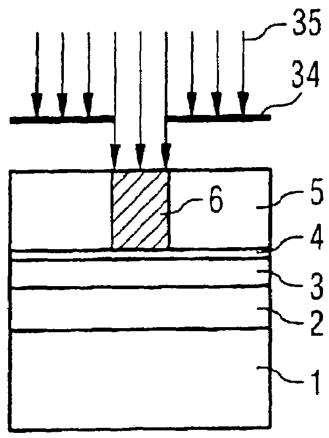
nitrogen contained in the underlying antireflection layer. This reliably prevents the situation where undesired interactions occur between the antireflection layer and the photoresist layer, in particular where penetrating nitrogen neutralizes acidic constituents of the resist or impedes the
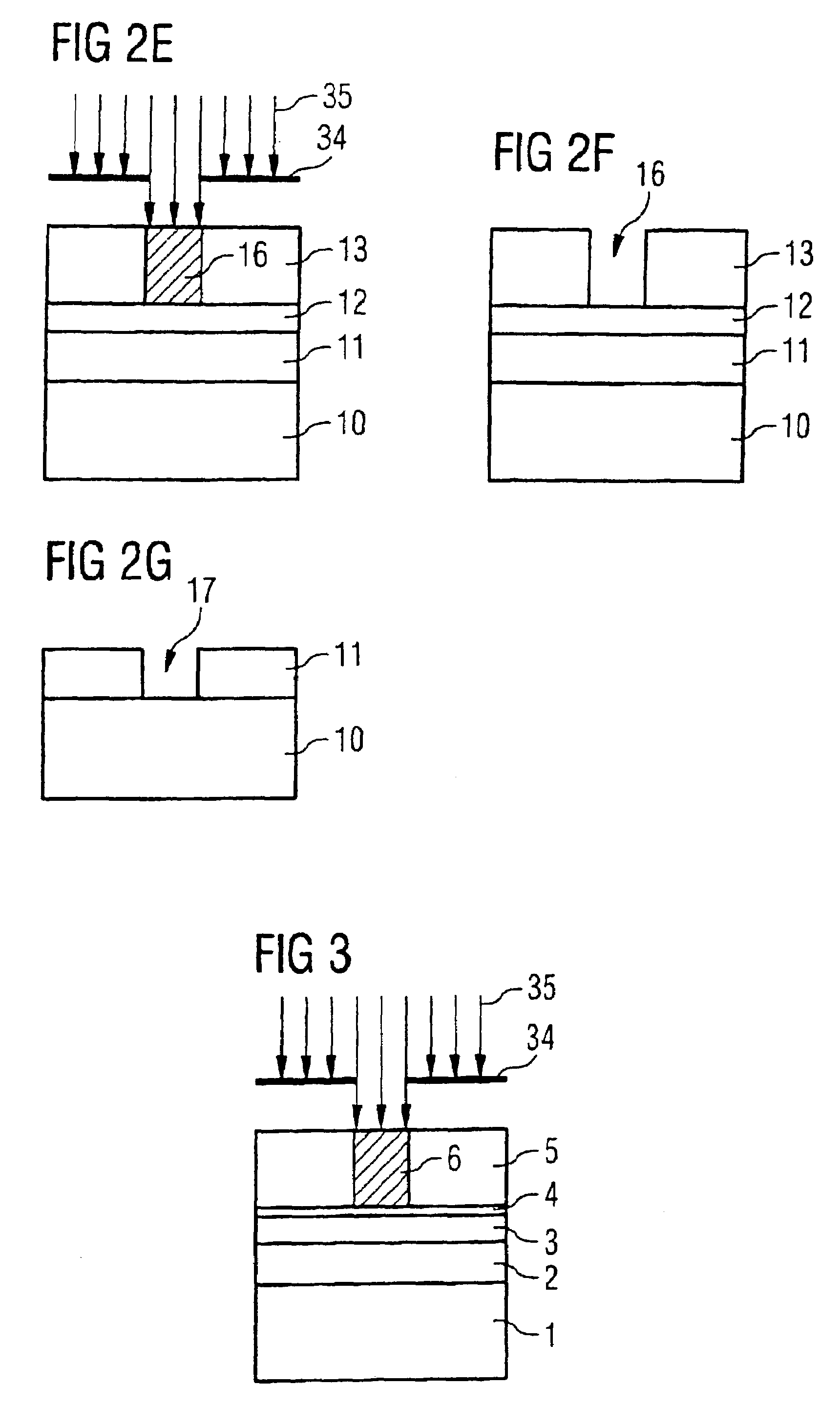
diffusion behavior of specific resist components and the photolithographic result could thus be adversely affected. The configuration according to the invention thus avoids the production of resist feet and thereby improves the dimensional accuracy of the transfer of the structure of an
exposure mask into a photoresist layer that is carried out during the
photolithography process. In this case, the SiOx layer may at the same time be configured such that the reflection conditions and thus the effect of the underlying
dielectric antireflection layer are not impaired or are even improved.
[0010]According to the invention, the method for fabricating a patterned layer may also be configured such that a Si-rich N-free SiOx layer where x is less than 2 is applied as a
dielectric antireflection layer directly on the semiconductor layer to be patterned, the photoresist layer then being produced on said SiOx layer. The use of an N-free dielectric antireflection layer composed of SiOx completely avoids any influencing of the photoresist by
neutralization of acidic constituents, with the result that there is no longer the risk of resist degradation.
[0011]The optical properties of the grown SiOx layer, i.e. the
extinction coefficient k, which determines the absorption behavior, and the
refractive index n, can be determined in a simple manner by setting or varying the Si content during the growth of the SiOx layer. This makes it possible, in a simple manner, to produce an adapted, optimally coordinated dielectric antireflection layer made of SiOx for the photoresist respectively applied.
[0012]As an alternative, when using an SiOx layer as an additional covering layer on an N-containing dielectric antireflection layer, it is possible, through suitable variation of the Si content, to form the SiOx layer such that it is slightly absorbent, thus resulting in the
advantage of a double antireflection layer in which the lower actual antireflection layer is more highly absorbent in order to minimize the reflection influence of the base, and the upper SiOx additional layer enables an optimum
optical coupling to the photoresist and thus an optimum interference
extinction.
[0014]In accordance with a further preferred embodiment, the SiOx layer formation is carried out in a reactor with a
high plasma density and a separate gas inlet for SiH4 and O2, the SiH4 flow being effected in an
order of magnitude of 5 sccm to 100 sccm, preferably of 13 sccm, the O2 flow being effected in an
order of magnitude of 5 sccm to 100 sccm, preferably of 10 sccm, an
inert gas flow, preferably with
argon, being effected in an
order of magnitude of 5 sccm to 1000 sccm, preferably of 50 sccm, a pressure in a
reaction chamber being set to 1 mTorr to 10 mTorr, preferably 1.2 mTorr, a power being set to 1 kW to 5 kW, preferably 3 kW, and a temperature of 250 to 550° C., preferably of 400° C., being set. The use of a so-called HDP chamber gives rise to the possibility of mixing SiH4 and O2 in a defined manner only in the reaction space and of exciting them differently in the
plasma, as a result of which the incorporation ratio of
silicon to
oxygen in the SiOx layer can be set precisely and an optimum N-free SiOx layer with corresponding optical properties can thus be produced.

