
Optical and optoelectronic articles

a technology of optical and optoelectronic articles and films, applied in the direction of glass optical fibres, cladded optical fibres, instruments, etc., can solve the problem that glass used in some optical fibers does not readily bond to metals to form fiber optic packages, and achieve the effect of enhancing the high temperature stability of films

Inactive Publication Date: 2006-09-12
3M INNOVATIVE PROPERTIES CO
View PDF49 Cites 15 Cited by
  • Summary
  • Abstract
  • Description
  • Claims
  • Application Information

AI Technical Summary

Benefits of technology

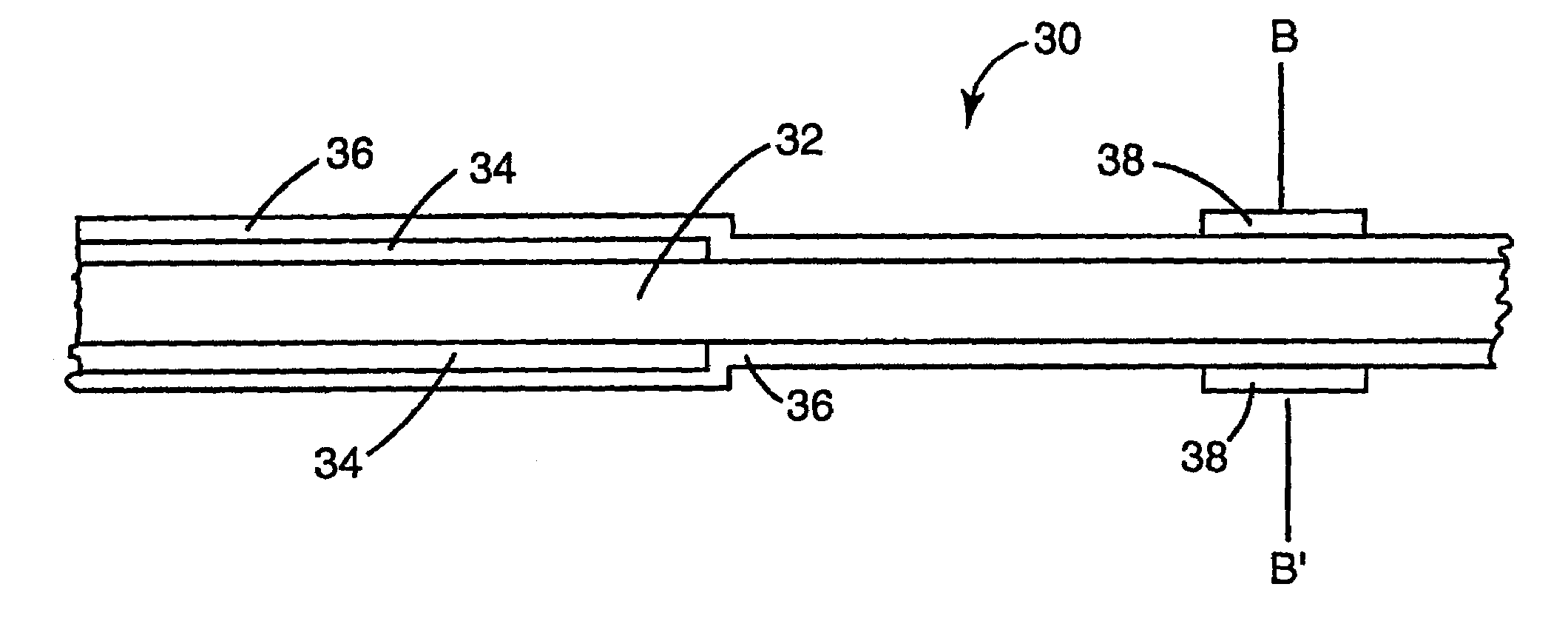
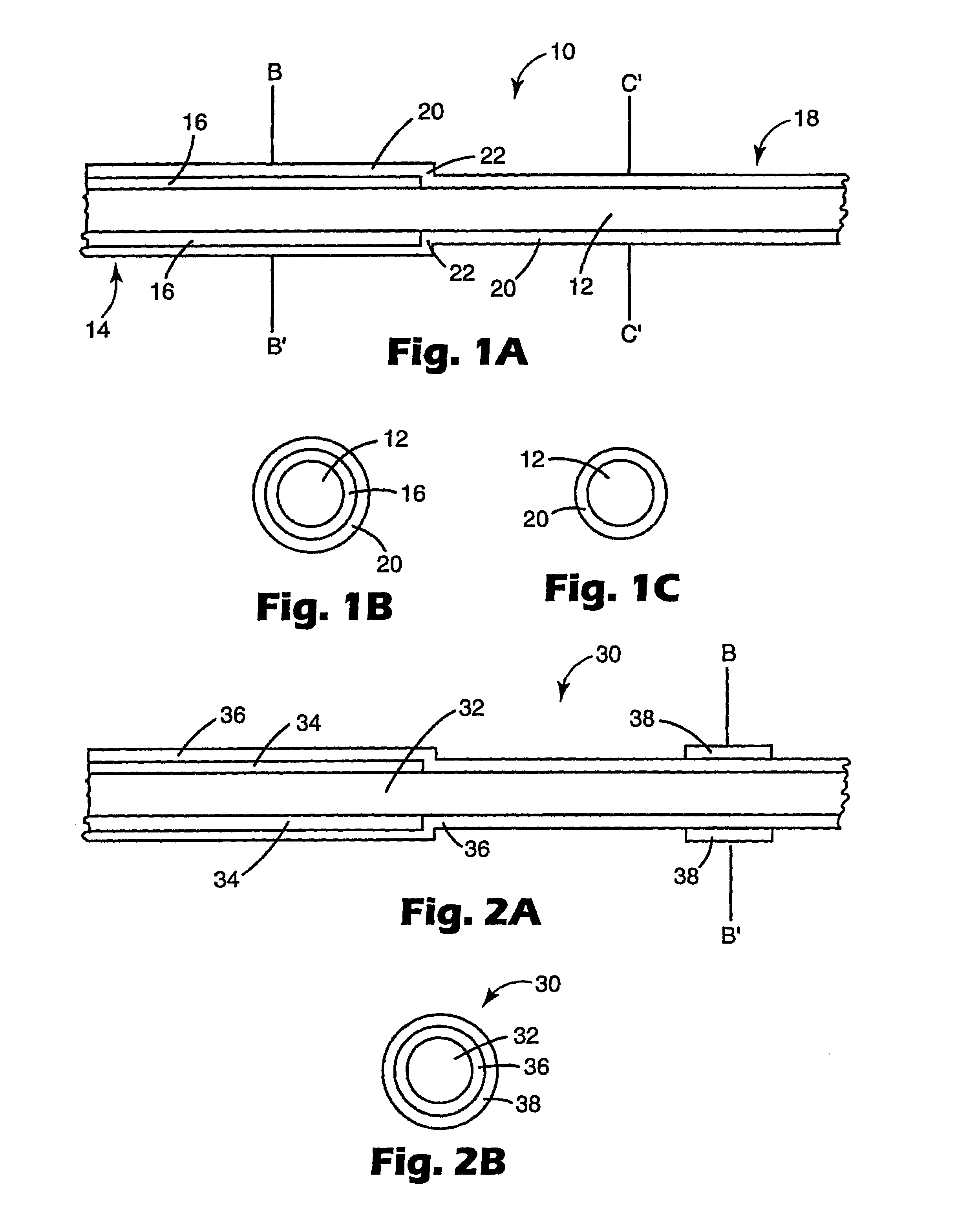
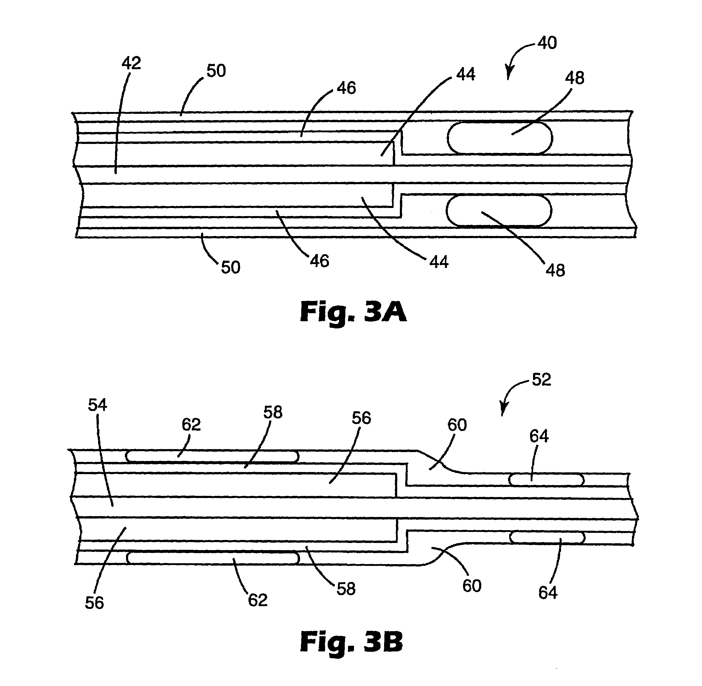
[0008]Generally, the articles of the invention include an optical glass substrate and an optional polymeric substrate. When both substrates are present, the optical glass substrate can be, for example, an optical fiber, and the polymeric substrate can be a coating on a portion of the optical fiber. An amorphous diamond-like film may be deposited on at least a portion of the glass and polymeric substrates, improving the properties of the articles by forming a strong protective layer over both substrates. The diamond-like film is advantageous in that it can protect the materials on which it is deposited while providing additional sealing at the transition from the glass substrate to the polymeric substrate. The diamond-like film also provides a substrate onto which additional materials may be coated or deposited. For example, a metallic layer is deposited onto the diamond-like film in certain embodiments of the invention. Similarly, the diamond-like film can be bonded to other components by soldering, use of a glass frit, or by laser welding. In this manner it is possible to form strong, durable, hermetic seals between materials in the optical components. It is also possible to form packages that have stable, durable attachments to other components in an optoelectronic article.
[0014]Optionally pre-treatment or post-treatment steps may be employed. Pre-treatment steps include cleaning the surface of a substrate before deposition. Post-treatment includes annealing the deposited film. High temperature stability of the films can be enhanced with combinations of pre-treatment and post-treatment operations.

Problems solved by technology

The transitions and interfaces in these optical components can present challenges to creating a durable, well-functioning product because they must be well sealed in order to prevent contamination from the environment (such as the entry of water or organic materials as either liquids or gases).
Also they must be strong and durable, which can be a challenge because some materials do not readily bond to one another even though they are desirably placed in contact.
For example, the glass used in some optical fibers does not readily bond to metals to form fiber optic packages.

Method used


Image

  • Optical and optoelectronic articles
  • Optical and optoelectronic articles
  • Optical and optoelectronic articles

Examples


example 1

[0090]This example illustrates the effect of DLG thin films as packaging materials for fibers.

[0091]Ten samples were made using acrylate-coated optical fibers (comprising an optical core of Germanium-doped silica with a pure silica cladding, the optical core being the most inner portion of the glass fiber and having a higher refractive index than the pure silica so the total internal reflection can occur to allow the construction to function as an optical fiber), having nominal core diameters of 5 to 10 μm, cladding diameters of 125 μm, and acrylate coating diameters of 250 μm, (the fibers being available as Part No. CS-00-5001 from 3M Company—Optical Components Program, West Haven, Conn.). The fibers were stripped by dipping a 6 cm section of a long length of fiber sequentially into fuming sulfuric acid (at 175° C.) then water. For each sample the section of fiber was submerged in each liquid for about 30 seconds.

[0092]Plasma Reactor One was used to deposit a film on the fibers. Th...

example 2

[0096]This example illustrates that DLG can be made with increased high temperature durability.

[0097]DLG thin films were deposited onto Pyrex glass slides using a pre-cleaning step, a deposition step similar to that of Example 1, and a post-annealing step. Adhesive tape was placed over part of each glass slide surface to provide an uncoated surface area for deposition thickness measurement. Pre-cleaning was done with an oxygen plasma at between 8.6 and 9.3 Pa (65 and 70 mTorr) and 2599 Watts for 2 minutes with an oxygen flowrate of 100 sccm.

[0098]Deposition of a DLG thin film onto the cleaned slides was done in a manner similar to that of Example 1 except Plasma Reactor Two was used and some process conditions were changed. The flowrates of TMS and oxygen were 150 sccm and 100 sccm, respectively. The pressure and power were maintained at 40 Pa (300 mTorr) and 1500 Watts, respectively, and the cleaned glass slide was exposed to the plasma for 10 minutes. The adhesive tape was removed...

example 3

[0101]This example illustrates that a post plasma treatment can be applied.

[0102]DLG thin films were deposited onto partially stripped optical fibers as in Example 1, using Plasma Reactor One. Then the DLG film was treated with oxygen plasma in Plasma Reactor Two. The oxygen plasma was formed with an oxygen flow rate of 500 sccm and an electrode power of 2000 W in a reactor vessel with a pressure of 9.3 Pa (70 mTorr). Treatment was carried out for 75 seconds. The sample was then flipped over and treated for another 75 seconds. The metalization was performed as described in Example 1.


PUM

PropertyMeasurementUnit
Temperatureaaaaaaaaaa
Thicknessaaaaaaaaaa
Percent by atomaaaaaaaaaa

Abstract

Optical and optoelectronic articles incorporating an amorphous diamond-like film are disclosed. Specifically, the invention includes optical or optoelectronic articles containing an amorphous diamond-like film overlying two or more proximate substrates, and to methods of making optical and optoelectronic articles. In certain implementations, the film comprises at least about 30 atomic percent carbon, from about 0 to about 50 atomic percent silicon, and from about 0 to about 50 atomic percent oxygen on a hydrogen-free basis. Another embodiment includes optical or optoelectronic articles containing an amorphous diamond-like film that is further coated with a metallic or polymeric material for attachment to a device package.

Description

CROSS REFERENCE TO RELATED APPLICATION[0001]This application claims the benefit of U.S. Provisional Application No. 60 / 323,233, filed Sep. 19, 2001, which is hereby incorporated by reference.TECHNICAL FIELD[0002]The present invention relates to articles containing diamond-like films and to methods of making optical and optoelectronic articles containing diamond-like films.BACKGROUND[0003]Modem electronic equipment, such as optical components used in fiber optics communications, often contains numerous materials having distinct physical properties. A single optical component can contain organic polymers, glass, and metals all fused together into one article. An example of such articles is a fiber optic pigtail used to splice fiber optic components together. Each pigtail is likely to combine numerous different materials having multiple transitions between materials and interfaces where two or more materials come in contact with one another.[0004]The transitions and interfaces in these...

Claims


Application Information

Patent Timeline
IPC IPC(8): G02B6/00C03C17/22C03C25/42C23C16/26C23C16/509C23C16/54G02B1/10G02B6/02G02B6/42G02B6/44
CPCC03C17/22C23C16/26C23C16/509G02B1/105G02B6/4248G02B6/02395C23C16/545C03C2217/282Y10T428/30G02B1/14
Inventor LABRAKE, DWAYNE L.GATES, BRIAN J.CRONK, BRYON J.DAVID, MOSES M.NELSON, BRIAN K.MILLER, MICHAEL N.BRENNAN, III, JAMES F.
Owner 3M INNOVATIVE PROPERTIES CO
Learn More