Method and device for multi photon excitation of a sample

Inactive Publication Date: 2006-10-03
MAX PLANCK GESELLSCHAFT ZUR FOERDERUNG DER WISSENSCHAFTEN EV
View PDF5 Cites 20 Cited by
  • Summary
  • Abstract
  • Description
  • Claims
  • Application Information

AI Technical Summary

Benefits of technology

[0024]The beam directing means may comprise at least one deviation element which modulates the phase of at least one of the partial beams by varying its paths length. This deviation element can, for example, be a mirror supported by an piezo element the position of which is periodically moved by actuating the piezo element over a distance which is longer than the wavelength of the partial beam.

Problems solved by technology

This results into an interference pattern in which the areas of maximum and minimum intensity do not show a sequence in the

Method used


Image

  • Method and device for multi photon excitation of a sample
  • Method and device for multi photon excitation of a sample
  • Method and device for multi photon excitation of a sample

Examples


Embodiment Construction

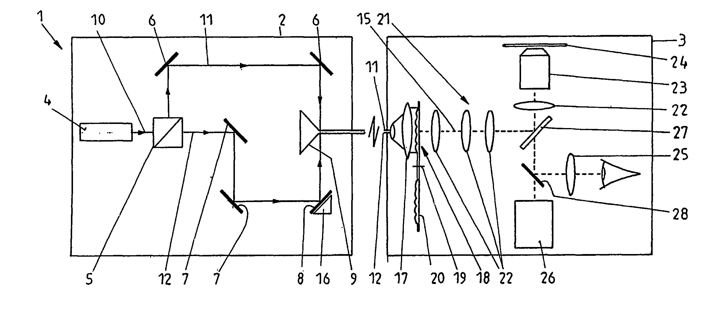
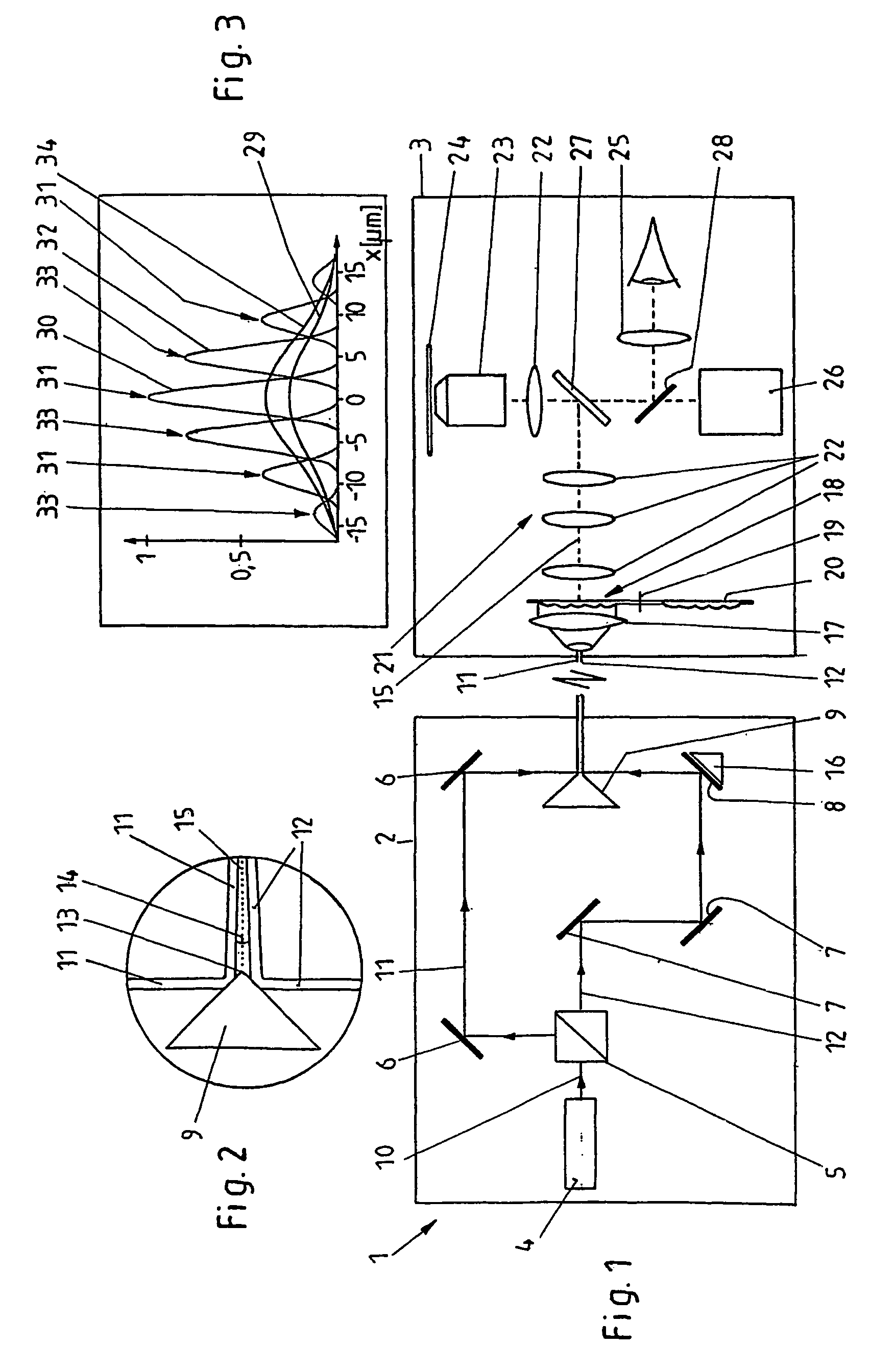
[0035]Referring now in greater detail to the drawings, the device 1 shown in FIG. 1 consists of two partial arrangements 2 and 3, the areas of which are each enclosed by a line in the present drawing. This does, however, not mean that the partial arrangements 2 and 3 have to be placed in different housings, or that there has to be another spatial or physical separation. The subdivision of the device 1 into the partial arrangements 2 and 3 only relates to their function.

[0036]The partial arrangements 2 of the device 1 includes a laser 4, a beam splitter 5, deviation mirrors 6, 7 and 8, and a roof mirror 9. The laser 4 emits a coherent laser beam 10. The beam splitter 5 splits the laser beam 10 into two partial beams 11 and 12 which are coherent with regard to each other and which each have a same intensity distribution about their beam axes. The partial beams 11 und 12 are deviated by means of the deviation mirrors 6 to 8, and they are directed towards the roof ridge 13 of the roof m...


PUM


Abstract

In a method for multi photon excitation of a sample a laser beam is split into at least two coherent partial beams each having a beam axis and a same intensity distribution about its beam axis. The partial beams are directed from different directions towards a common measuring plane running transversely to the beam axes at an inclination angle <1 between the beam axes of the partial beams; and the partial beams are projected onto the measuring plane by means of a common lens system. Thus, an interference pattern formed by the coherent partial beams within the measuring plane provides areas of maximum light intensity adjacent to areas of minimum light intensity.

Description

CROSS REFERENCE TO RELATED APPLICATIONS[0001]This application is a continuation in part of International Patent Application PCT / EP02 / 03785 filed Apr. 5, 2002 and claiming priority to co-pending German Patent Application No. 101 18 355.0-42 filed Apr. 12, 2001 both of which are entitled “Verfahren und Vorrichtung zur Mehrphotonenanregung einer Probe”.FIELD OF THE INVENTION[0002]The present invention generally relates to a method for multi photon excitation of a sample, comprising the steps of splitting a laser beam into at least two coherent partial beams each having a beam axis and a same intensity distribution about its beam axis, directing the partial beams in different directions, and projecting the partial beams from different directions onto a common measuring plane running transversely to the beam axes, an interference pattern being formed by the coherent partial beams in the area of the measuring plane.[0003]Further, the invention relates to a device for multi photon excitati...

Claims


Application Information

Patent Timeline
IPC IPC(8): G01T1/10G01N21/64G02B21/00G02B21/06
CPCG01N21/6402G01N21/6458G02B21/002
Inventor HELL, STEFAN
Owner MAX PLANCK GESELLSCHAFT ZUR FOERDERUNG DER WISSENSCHAFTEN EV
Why Eureka
Try Eureka