Apparatus and method for bioelectric stimulation, healing acceleration, pain relief, or pathogen devitalization

a bioelectric stimulation and apparatus technology, applied in the field of pulsed signal generators, can solve the problems of decreased productivity, inconvenience of function loss, expense, etc., and achieve the effect of accelerating healing and minimizing stress

Active Publication Date: 2006-10-03
HEALTHONICS INC
View PDF46 Cites 467 Cited by
  • Summary
  • Abstract
  • Description
  • Claims
  • Application Information

AI Technical Summary

Benefits of technology

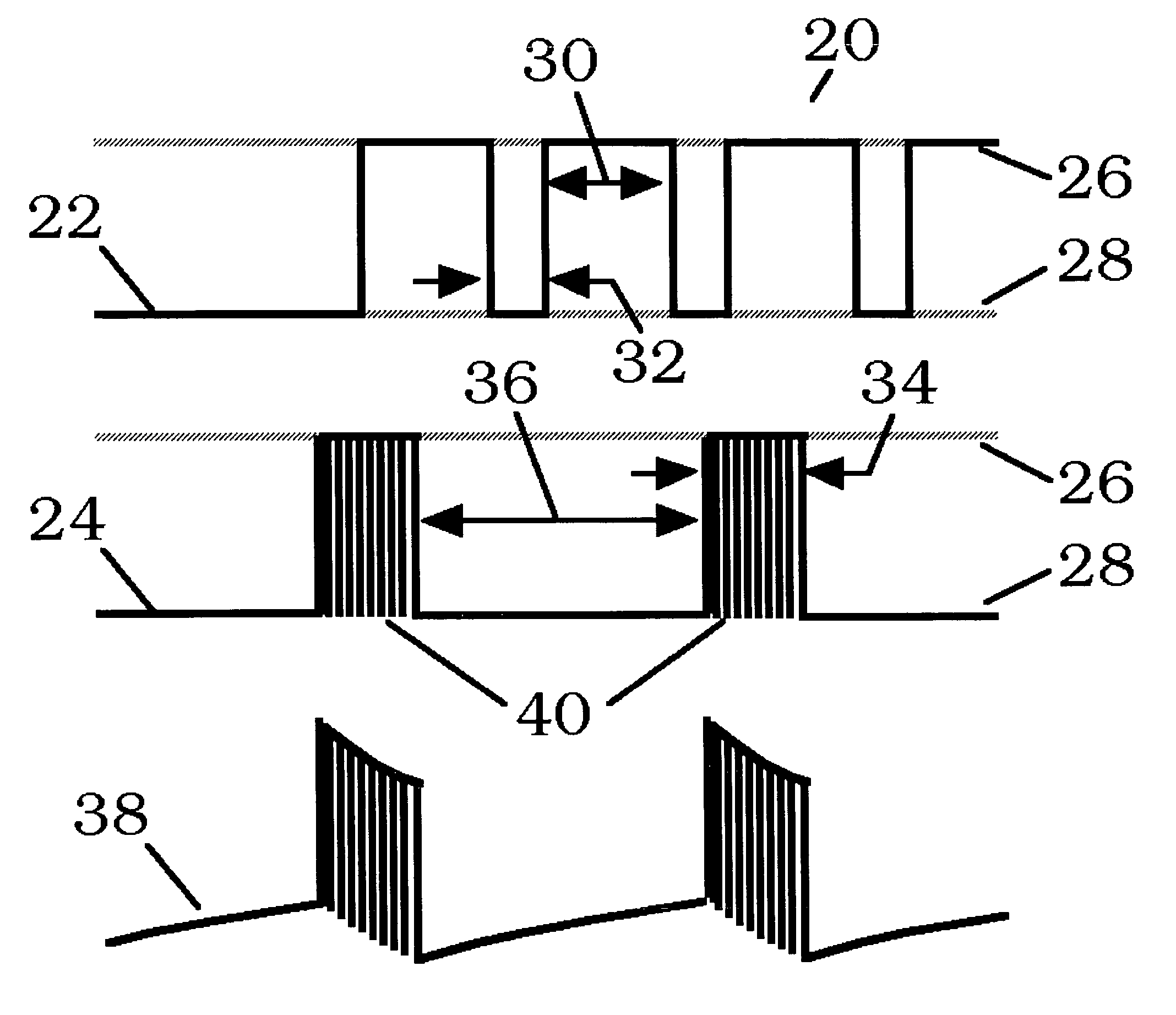
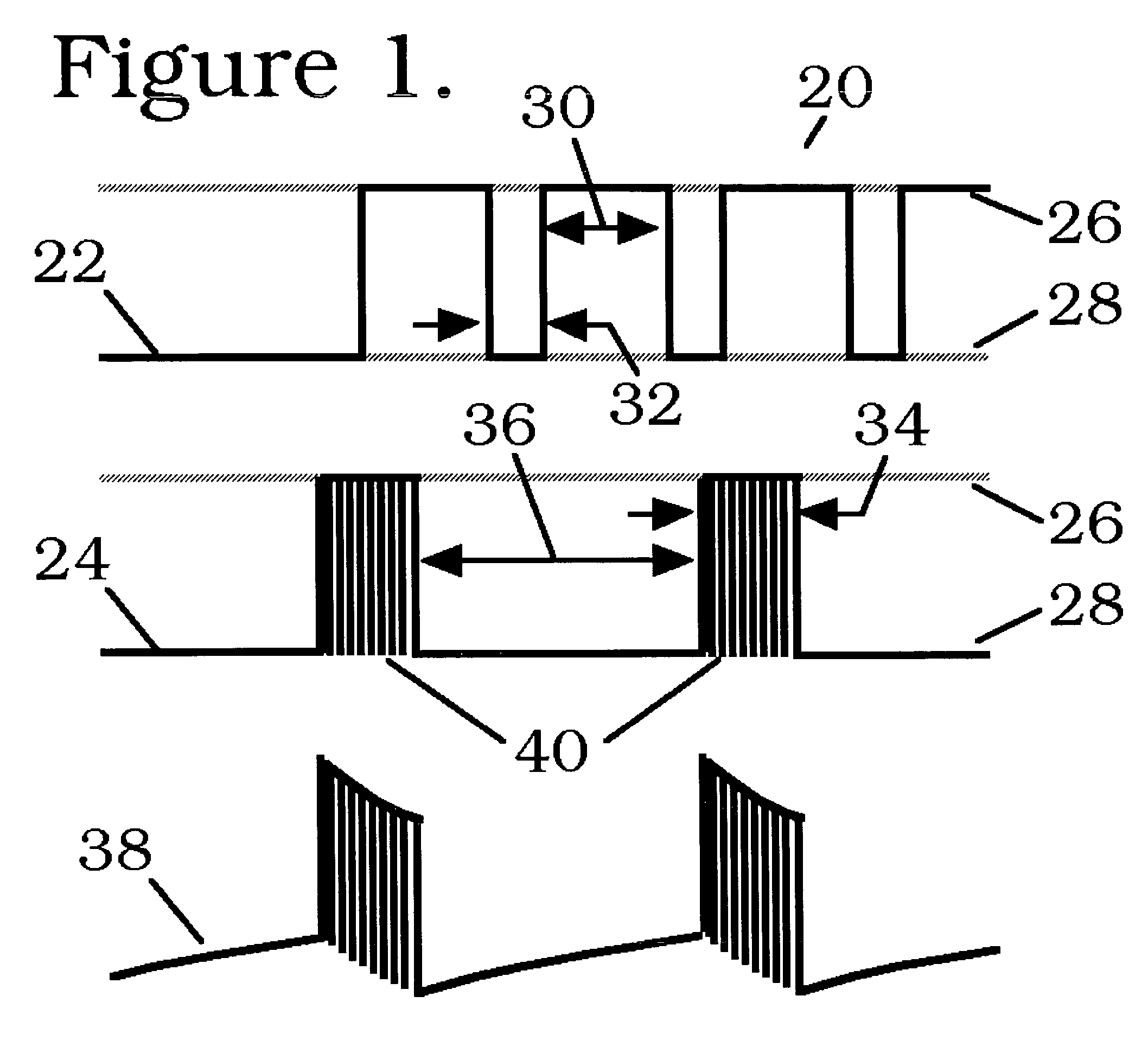
[0044]According to its major aspects and broadly stated, the present invention comprises an apparatus and method for generating an electrical signal for use in biomedical applications. The present invention provides devices and methods for alleviating a wide variety of health problems in both humans and animals. In contrast to prior art devices which typically ...

Problems solved by technology

Injuries, infections and degenerative conditions are major sources of pain, lost function inconvenience, expense, lost work (and leisure) time, and diminished productivity.
The problems associated with these conditions grow worse with age, since an injury which would heal quickly in a young, healthy person takes much longer in one who is older, in poor health, or both.
While it is difficult to estimate the total cost of such conditions, leaving aside their impact on quality of life, the total surely amounts to many billions of dollars per year in the United States alone.
Even after the cast is removed, the patient's activities are frequently restricted until the healed bone regains its full strength.
As a result, an estimated quarter-million person-years of productivity are lost in the United States every year due to bone fractures alone.
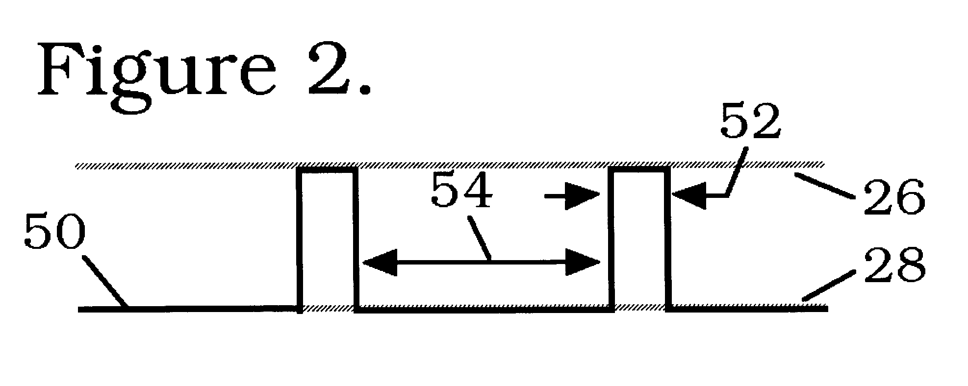
The signal intensity may also vary; indeed, more powerful signals often give no more benefit than weaker ones, and sometimes less.
Beyond point 64, the signal may slow healing or may itself cause further injury.
For example, while conventional TE...

Method used


Image

  • Apparatus and method for bioelectric stimulation, healing acceleration, pain relief, or pathogen devitalization
  • Apparatus and method for bioelectric stimulation, healing acceleration, pain relief, or pathogen devitalization
  • Apparatus and method for bioelectric stimulation, healing acceleration, pain relief, or pathogen devitalization

Examples


example 1

Bioelectrical Stimulation of Fractured Bones

[0329]A 50 year old male was injured in a motorcycle accident that resulted in spiral fractures of his tibia and fibula. The tibia was fractured approximately 3″ above the article while the fibula was fractured from the top of the bone. At the time of the accident the male was in otherwise good health and sustained no other injuries. X-rays and the evaluation in the emergency room confirmed the double fractures. It was determined that surgery to correct the problem would be required. An appointment was set for the following morning with the orthopedic surgeon. Surgery was scheduled and performed the afternoon of February 4. A sterile steel nail was inserted down the shaft of the tibia running the full length of the bone. Two screws secured the nail at the top of the tibia while three screws secured it at the ankle. The patient was originally scheduled for two nights in the hospital but was released approximately 24 hours following the surg...

example 2

Bioelectrical Stimulation of Fractured Bone in Animal

[0336]An injured German-Shepherd mix was successfully treated through bioelectrical stimulation using the waveform substantially as shown in FIG. 6 as detailed below.

[0337]It was found that a bullet had struck the dog in her right front femur and shattered its middle section into many small pieces. The bullet appeared to be 0.22 caliber, and had mushroomed on impact, then fragmented further, with many lead pieces clearly visible on an X-ray.

[0338]Under anesthesia a half shell, fiberglass Spica splint was placed with heavy cast padding. The predicted recovery time was at least four and more likely six weeks or more. The veterinarian warned that the dog would probably have a permanent limp. No attempt was made to remove the bullet.

[0339]An X-ray after two weeks of MedRelief™ treatment showed the bone fragments completely reunited, now encasing the major bullet fragments. The fracture already showed excellent callus and stabilization...

example 3

Bioelectrical Stimulation of Deep Skin Abrasions

[0341]The subject of this study had suffered three abrasive injuries on the backs of his hands. The wounds were received at the same time, in the same way, and were of about the same severity. Of the three wounds, the one that was the most severe was selected for the MedRelief™ treatment, bioelectrical stimulation comprising application of the waveform substantially as shown in FIG. 6.

[0342]The wounds were cleaned of visible debris using soap and water, but no antibiotics or disinfectants were used. Treatment was for about eight hours at a time, during sleep.

[0343]After the first night all of the wounds were scabbed over, the areas around them swollen and painful to the touch, but the treated one was noticeably worse than the others. (It is impossible to say whether this resulted in part from the action of MedRelief™, or simply from that wound's having been more severe in the first place.) The pain and sensitivity of the treated area g...


PUM


Abstract

An method and method for generating an electrical signal for use in biomedical applications, including two timing-interval generators, each optionally driving a multistep sequencer; analog, digital or hybrid means for combining the resulting timed signals into a complex electrical signal; optional filtering means for blocking direct current, removing selected frequency components from the resulting signal, and/or providing voltage step-up if needed; and conductive means for coupling the resulting signal to a human or animal body, food, beverage or other liquid, cell or tissue culture, or pharmaceutical material, in order to relieve pain, stimulate healing or growth, enhance the production of specific biochemicals, or devitalize selected types of organisms.

Description

CROSS-REFERENCE TO RELATED APPLICATIONS[0001]The present application claims benefit of U.S. Provisional Application Ser. No. 60 / 480,890 filed Jun. 24, 2003.TECHNICAL FIELD OF THE INVENTION[0002]The present invention relates to a pulsed signal generator for biomedical applications. In particular, the present invention relates to a light-weight, compact pulsed signal generator that produces unique output waveforms based on a plurality of relatively long primary timing intervals T1, T2 and so forth, forming in succession a primary repeating cycle; a plurality of shorter secondary timing intervals t1, t2 and so forth, into which at least one of said primary intervals is divided, and forming in succession a secondary repeating cycle which continues throughout the length of that primary interval, while at least one other of said primary intervals is not so divided; a plurality of constant voltage or current levels L1, L2 and so forth, one of which is selected during each primary or second...

Claims


Application Information

Patent Timeline
IPC IPC(8): A61N1/36A61N1/32A61N1/34
CPCA61N1/326A61N1/025A61N1/36071A61N1/36021A61N1/00A61N1/18A61N1/32
Inventor KRONBERG, JAMES W.
Owner HEALTHONICS INC
Why Eureka
Try Eureka