Phase contrast microscope for short wavelength radiation and imaging method

Inactive Publication Date: 2006-10-10
XRADIA
View PDF22 Cites 53 Cited by
  • Summary
  • Abstract
  • Description
  • Claims
  • Application Information

AI Technical Summary

Benefits of technology

[0010]According to the present invention, the phase plate is placed away from the objective's back focal plane and preferably in close proximity to the objective, instead of at the back focal plane of the objective as in the prior art. The close proximity facilitates the initial alignment between the zone plate and the phase plate, and the maintenance of that alignment over time. In one example

Problems solved by technology

One challenge that arises in the operation of these conventional phase contrast microscopes is achieving and maintaining alignment between the objective and the phase plate.
In the prior art devices, this alignment has been difficult to achieve during the initial assembly of the microscope and to maintain the alignment

Method used


Image

  • Phase contrast microscope for short wavelength radiation and imaging method
  • Phase contrast microscope for short wavelength radiation and imaging method
  • Phase contrast microscope for short wavelength radiation and imaging method

Examples


Example

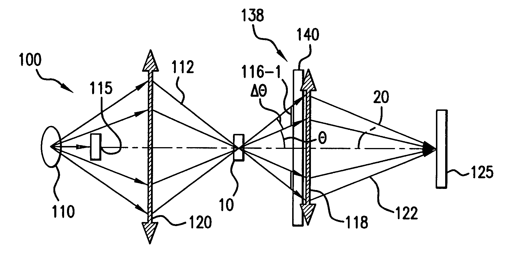
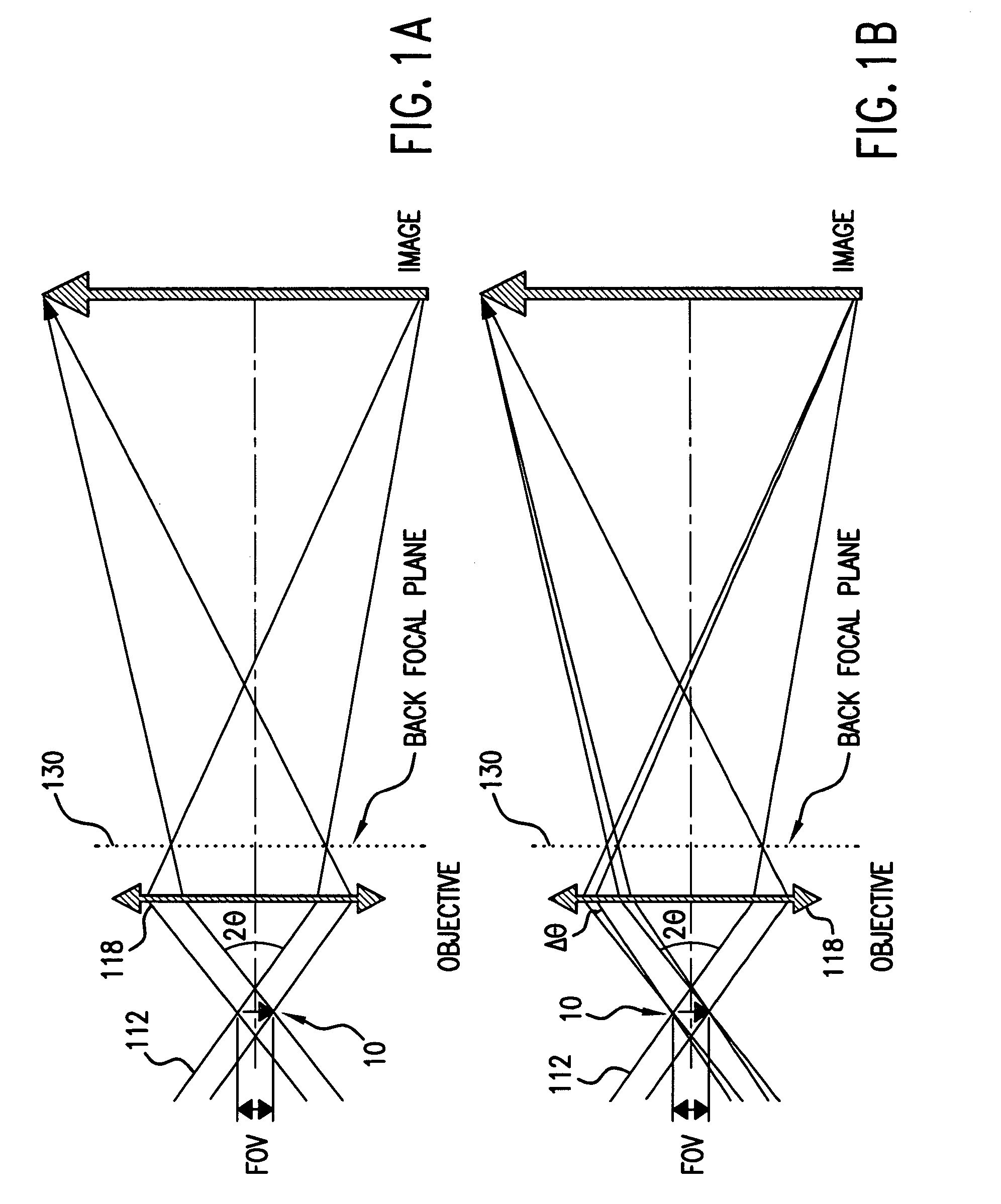
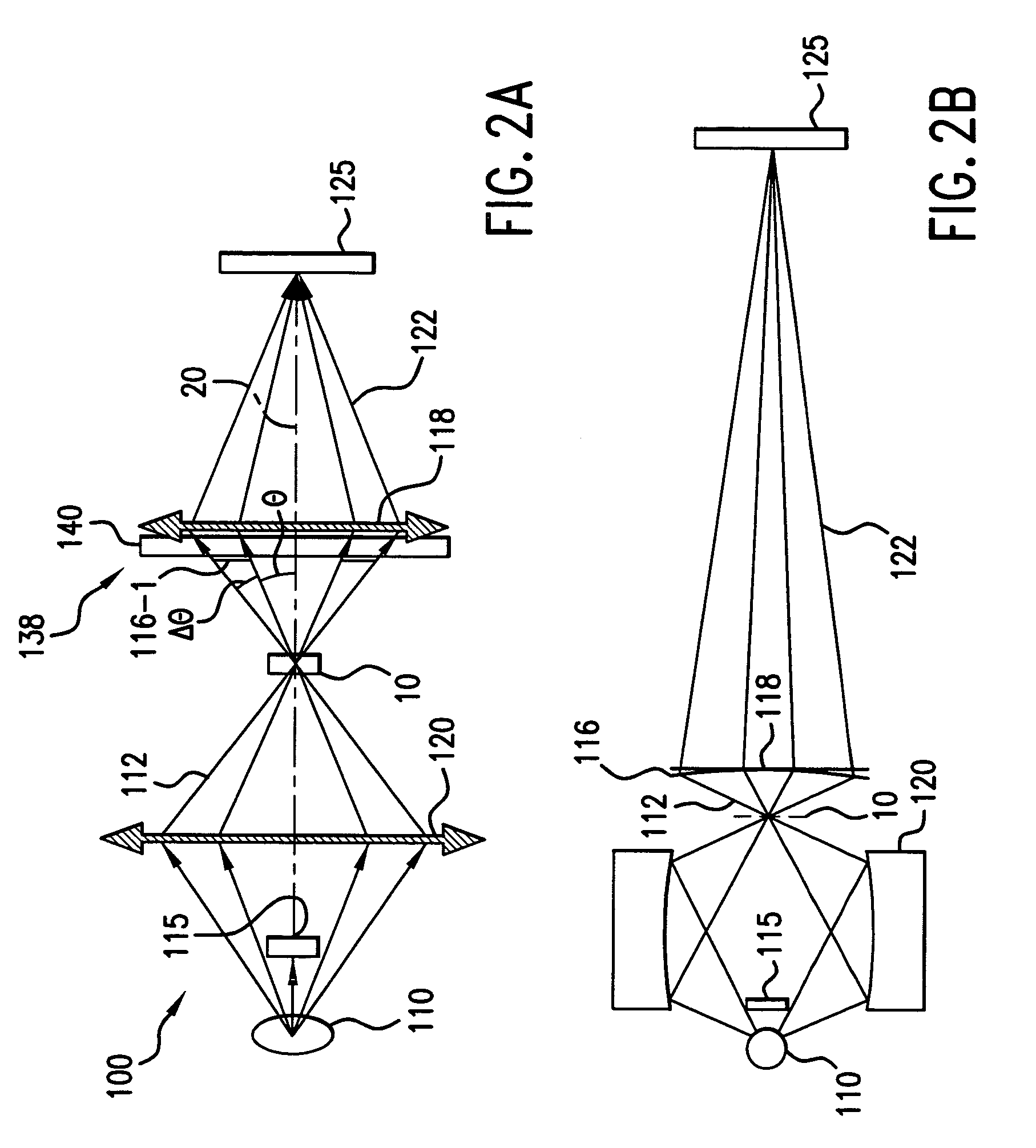
[0030]FIGS. 1A and 1B schematically illustrate why phase plates are placed at the back focal planes of objectives in the typical phase contrast microscope configuration and the validity conditions for the phase contrast imaging configuration according to the present invention.

[0031]Four important parameters characterize the illumination beam 112: 1) the brightness B, 2) the field of view (FOV), 3) the mean numerical aperture NAc,=sin θ, and 4) the angular spread Δθ.

[0032]The photon flux incident on the test object 10 within the field of view (FOV) is proportional to B*2π*(1−cos θ), which approximately equals to (B*2π*sin θ*Δθ) for small θ. The exposure time is inversely proportional to this photon flux.

[0033]The brightness B is typically constrained by the device used. The source brightness and the throughput of the optical system relaying the photons from the source to the test object 10 to thus produce the illumination beam 112 dictate the level of the brightness.

[0034]Thus, for a...


PUM


Abstract

A phase contrast x-ray microscope has a phase plate that is placed in proximity of and attached rigidly to the objective to form a composite optic. This enables easier initial and long-term maintenance of alignment of the microscope. In one example, they are fabricated on the same high-transmissive substrate. The use of this composite optic allows for lithographic-based alignment that will not change over the lifetime of the instrument. Also, in one configuration, the phase plate is located between the test object and the objective.

Description

BACKGROUND OF THE INVENTION[0001]Short wavelength microscopes are devices that produce a magnified image of an object utilizing electromagnetic radiation in the extreme ultraviolet (EUV) and x-ray regime. The wavelengths range from 20 nanometers (nm) to 0.02 nm. These microscopes typically develop image contrast by relying on photoelectric absorption in the test object. Different elements, or structures formed of elements, attenuate the x-rays to varying degrees.[0002]In a typical short wavelength microscope configuration, a focusing element, such as a condenser, is used to concentrate the radiation on the test object. An objective, such as a zone plate, collects the radiation after transmission through the object and forms an image on a detector, such as a charge-coupled device or film. Intervening scintillators are sometimes required, depending on the specific wavelength and detector used.[0003]Absorption-based x-ray microscopy, however, tends to impose certain limitations on the ...

Claims


Application Information

Patent Timeline
IPC IPC(8): G02B21/06G21K7/00G02B21/00G21K1/06
CPCA61B6/484G21K7/00G21K2207/005A61B6/4092Y10S359/90Y10S438/975
Inventor YUN, WENBINGWANG, YUXIN
Owner XRADIA
Why Eureka
Try Eureka