Valve controller

a valve controller and valve controller technology, applied in electrical control, non-mechanical valves, instruments, etc., can solve the problems of large size of valve controllers and increase production costs, and achieve the effect of reducing production costs

Inactive Publication Date: 2006-10-17
DENSO CORP
View PDF12 Cites 12 Cited by
  • Summary
  • Abstract
  • Description
  • Claims
  • Application Information

AI Technical Summary

Benefits of technology

[0006]An object of the present invention is to provide a valve controller which is compact and of which production cost is reduced. According to the present invention, a valve controller adjusts a valve characteristic utilizing a rotational torque of a motor. The valve controller includes a control circuit, a rotational position sensor and a driving circuit. The control circuit generates a control signal. The rotational position sensor detects a rotational position of the motor, and generates a rotational position signal. The driving circuit drives the motor based on the control signal and the rotational position signal, generates a rotation number signal which represents an actual rotation number of the motor based on the rotational position signal, and transmits the rotation number signal to the control circuit.

Problems solved by technology

Thus, the size of the valve controller becomes large and the production cost increases.

Method used


Image

  • Valve controller
  • Valve controller
  • Valve controller

Examples


first embodiment

[0022](First Embodiment)

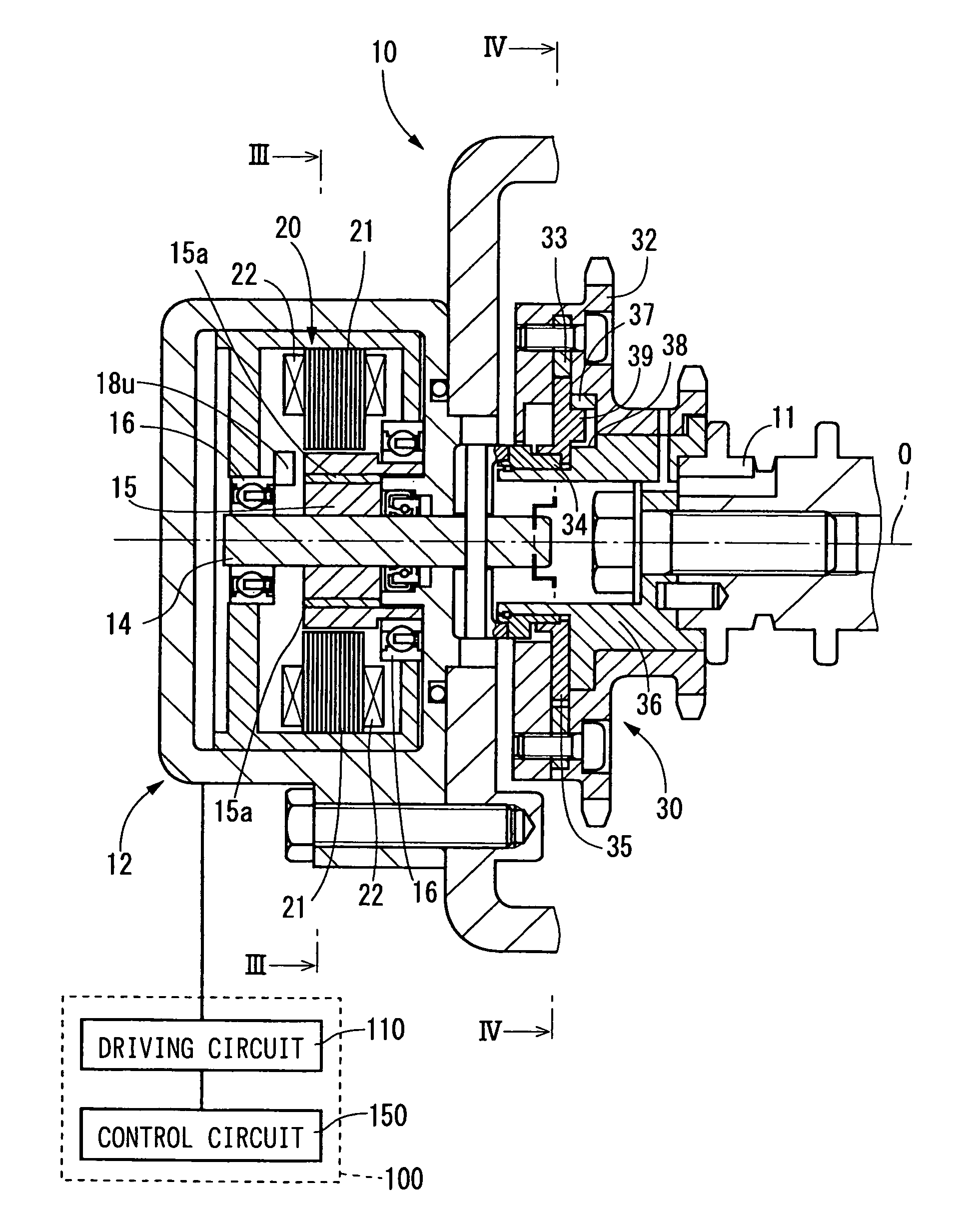
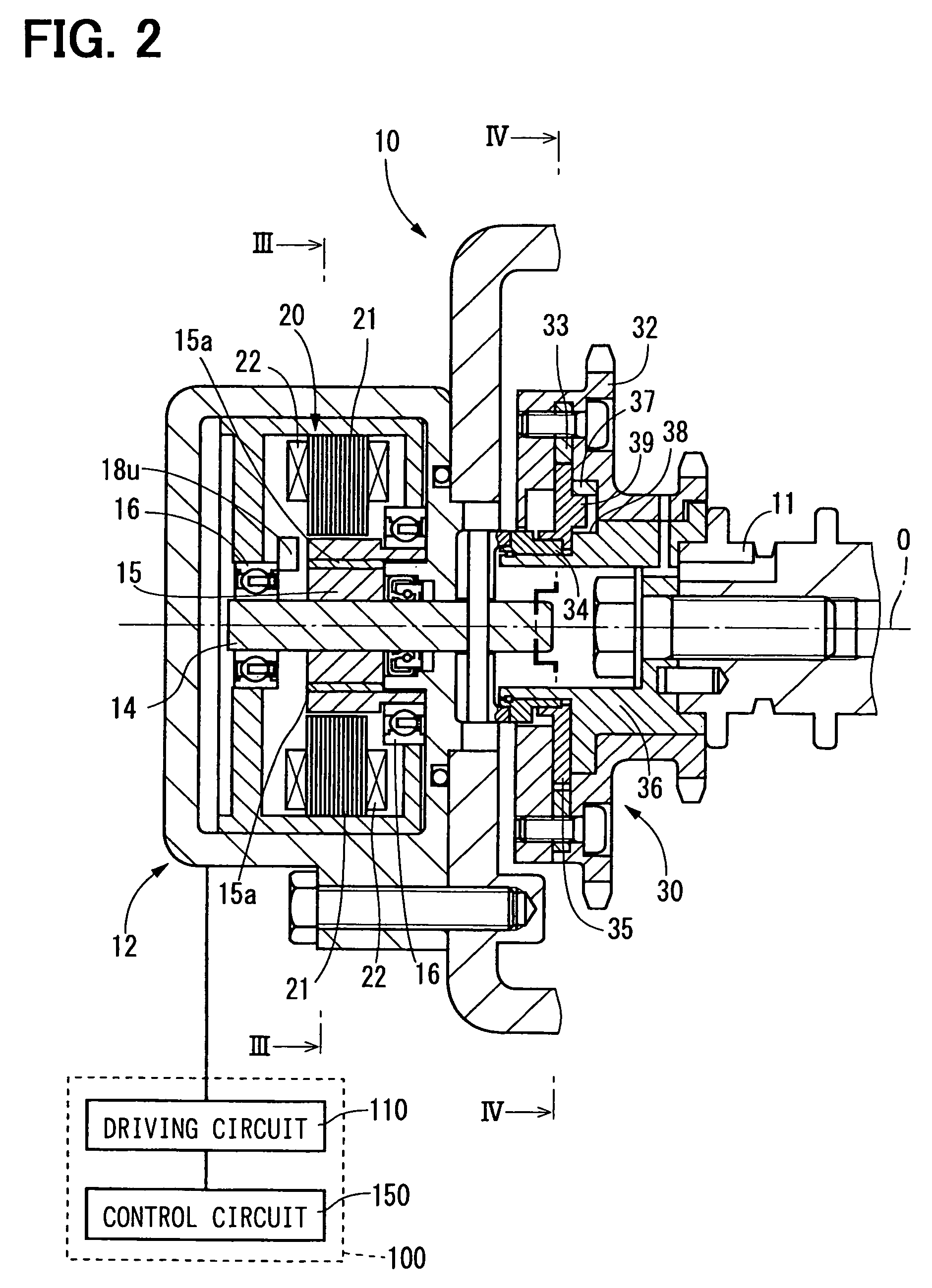
[0023]Referring to FIGS. 2 to 4, a first embodiment is described hereinafter. The valve timing controller 10 is disposed in a torque transfer system from a crankshaft to a camshaft 11. The valve timing controller 10, which is referred to as VTC 10 hereinafter, changes valve timing of the intake valve and the exhaust valve by utilizing a rotational torque of an electric motor 12 which is controlled by a motor control device 100.

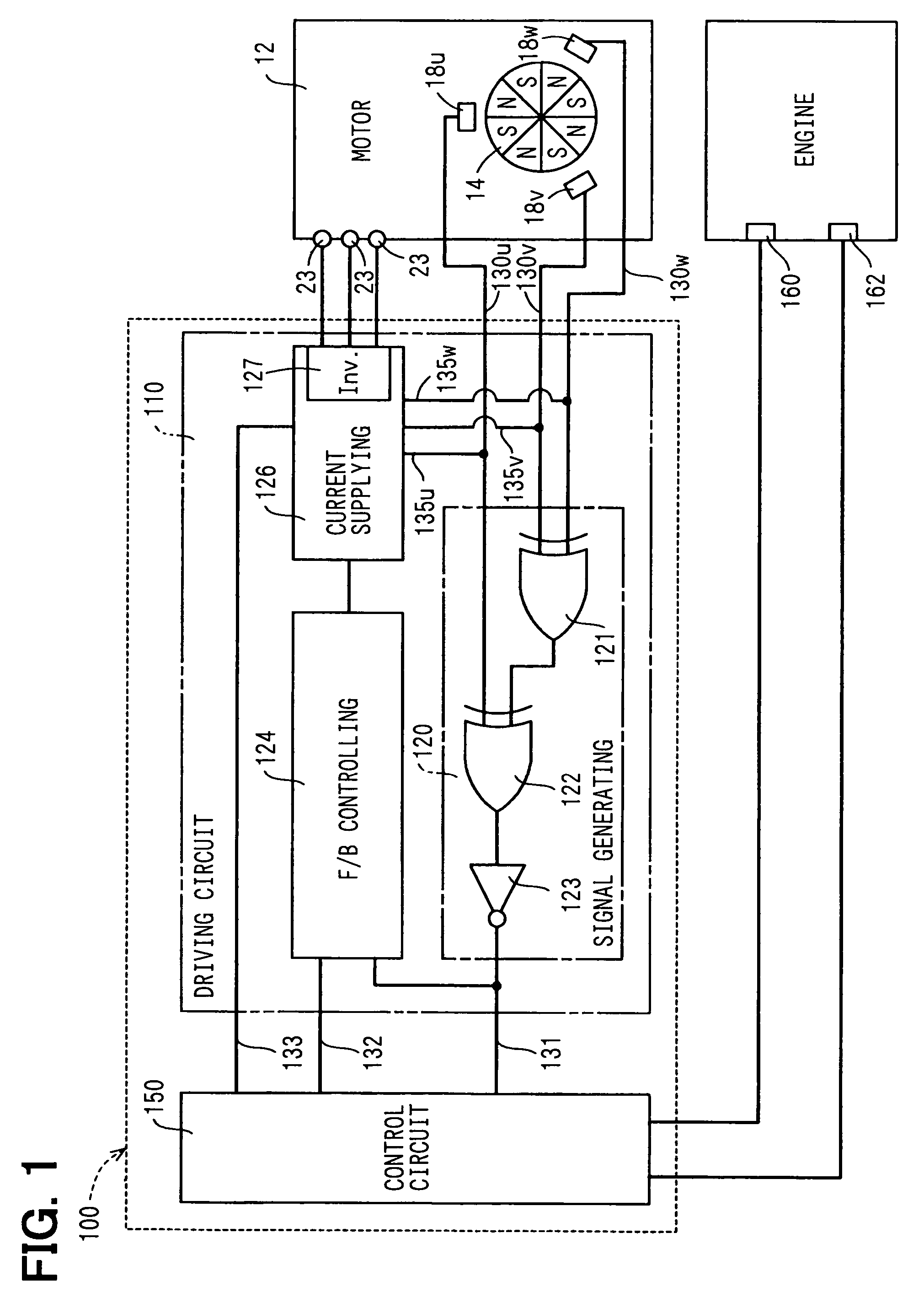
[0024]The electric motor 12 is a three-phase brushless motor having a motor shaft 14, a bearing 16, Hall effect devices 18u, 18v, 18w as rotational positioning sensors, and a stator 20.

[0025]The motor shaft 14 is supported by a pair of bearings 16 and rotates clockwise / counterclockwise around an axis “O”. In FIG. 3, when the motor shaft 14 rotates clockwise, it is called that the motor shaft 14 rotates in normal direction. When the motor shaft 14 rotates counterclockwise, it is called that the motor shaft 14 rotates in reverse directio...

second embodiment

[0049](Second Embodiment)

[0050]FIG. 8 shows a motor control device 200 for the VTC according to the second embodiment in which the same parts and components as those in the first embodiment are indicated with the same reference numerals and the same descriptions will not be reiterated.

[0051]The control circuit 210 configures a target load current Ia of the motor 12 and the target rotation direction Da for maintaining or changing the rotational phase. The target load current Ia represents necessary load current to rotates the motor shaft 14 in the target rotation direction. The rotation number of the motor shaft 14 for changing or maintaining the rotation number is calculated based on the rotation number of the crank shaft and the cam shaft 11 and the actual rotation number R. The target load current Ia is calculated to establish the rotation number considering the rotation number of the crank shaft or the camshaft 11, oil temperature, and the voltage of power source. The control cir...

third embodiment

[0056](Third Embodiment)

[0057]In the third embodiment, the present invention is applied to the valve lift controller 300. The valve lift controller 300 is referred to as VLC 300 hereinafter.

[0058]FIGS. 9 to 12 show essential parts of the VLC 300. The VLC 300 varies the maximum valve lift of an intake valve by utilizing rotational torque of a motor 320 which is controlled by a motor control device 370.

[0059]The VLC 300 includes an actuator 310 which linearly drives a control shaft 330 in an axial direction, and a valve lift mechanism (not shown) which changes the maximum valve lift of the intake valve according to the position of the control shaft 330.

[0060]As shown in FIG. 9, the actuator 310 is provided with a motor 320, the control shaft 330, a transfer mechanism 340, a driving cam 350 (FIG. 11), and the motor control device 370. The motor 320 and the motor control device 370 are modifications of the motor 120 and the motor control device 370 in the first embodiment.

[0061]The moto...


PUM


Abstract

The valve controller is driven by a motor. The valve controller has a control circuit and a driving circuit. The driving circuit drives a motor based on a control signal generated by the control circuit and a rotational position signal generated by a rotational position sensor. The driving circuit generates a rotation number signal representing an actual rotation number of the motor according to the rotational position signal, and transfers the rotation number signal to the control circuit.

Description

CROSS REFERENCE TO RELATED APPLICATION[0001]This application is based on Japanese Patent Applications No. 2003-350861 filed on Oct. 9, 2003 and No. 2004-128255 filed on Apr. 23, 2004, the disclosures of which are incorporated herein by reference.FIELD OF THE INVENTION[0002]The present invention relates to a valve controller for an internal combustion engine, which is driven by an electric motor. The valve controller changes valve timing or valve lift of an intake valve and / or an exhaust valve of the internal combustion engine.BACKGROUND OF THE INVENTION[0003]As shown in JP-U-4-105906A, the valve controller changes valve timing of an intake valve and / or an exhaust valve by rotational torque of an electric motor. Alternatively, the valve controller changes valve lift of an intake valve and / or an exhaust valve by rotational torque of an electric motor as shown in JP-11-324625A.[0004]In such a valve controller, an electric current supplied from a driving circuit to the motor is controll...

Claims


Application Information

Patent Timeline
Patent Type & Authority Patents(United States)
IPC IPC(8): F01L1/34F01L1/344F01L1/352F01L13/00F02D13/02F02D45/00
CPCF01L1/022F01L1/34409F01L1/352F01L13/0015F01L13/0042F01L2105/00F01L2201/00F01L2800/00F01L2820/041F01L2305/00
Inventor TANI, HIDEJI
Owner DENSO CORP
Why Eureka
Try Eureka