Solid electrolyte type fuel battery

a fuel battery, solid electrolyte technology, applied in the direction of electrochemical generators, sustainable manufacturing/processing, final product manufacturing, etc., can solve the problems of reducing the output characteristics of the fuel battery, lanthanum chromite, in particular, is difficult to burn, and the material does not fully meet the required properties, etc., to achieve excellent durability and reliability, and the effect of easy production

Inactive Publication Date: 2006-10-17
MITSUBISHI HITACHIPOWER SYST LTD
View PDF15 Cites 9 Cited by
  • Summary
  • Abstract
  • Description
  • Claims
  • Application Information

AI Technical Summary

Benefits of technology

[0012]The present invention has been accomplished in light of the various problems involved in the use of the interconnector for use in a solid electrolyte type fuel battery. The invention uses a material comprising a matrix of M

Problems solved by technology

This material does not completely fulfill the required properties, and has much to be improved, particularly, in terms of burning properties and cracking due to expansion during reduction.
Thus, some oxygen is drawn out on the reducing side, causing expansion.
As a result, a “warping” force works in the same material, resulting in fracture.
Lanthanum chromite, in particular, is difficult to burn, and is usually burned only at a burning temperature higher than 1,600° C. in a reducing or vacuum atmosphere.
This poses the problem that the por

Method used


Image

  • Solid electrolyte type fuel battery
  • Solid electrolyte type fuel battery
  • Solid electrolyte type fuel battery

Examples


example 1

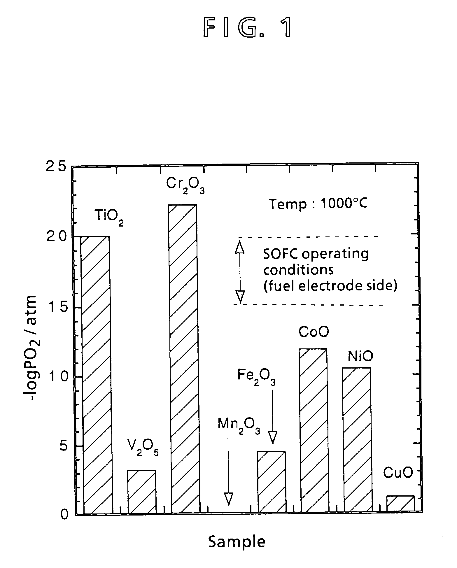
[0072]In inventing an interconnector different from a conventional lanthanum chromite interconnector, materials were preliminarily selected. Aside from lanthanum chromite, a material for an interconnector that fulfills thermal expansion characteristics, electric conductivity characteristics, and reduction expansion characteristics is selected in accordance with the following criteria:[0073]① Be an oxide (a metal other than the platinum group or even a nonoxide system ceramic is oxidized in the air of 1,000° C.).[0074]② Be a composite oxide (properties of a single-element oxide are difficult to control).[0075]③ Requires a transition metal (an element having a d-orbit electron) for imparting electric conductivity.

[0076]Lanthanoid series elements and actinoid series elements are difficult to accept because of a great energy gap and radioactivity, respectively. Second and third transition metals are also difficult to adopt because of their limited amounts as resources and firing propert...

example 2

[0092]Next, the present invention will be described in further detail with reference to concrete examples using MgTiO3 system interconnectors.

[0093]Example 1 shows that MgTiO3 system interconnectors exhibit better characteristics than lanthanum chromite. When an interconnector is to be used industrially for a solid electrolyte fuel battery, there is need to use interconnector materials mass produced by the ball mill mixing method described below, rather than the mortar mixing method mentioned in Example 1. Example 2 offers a more detailed explanation for the method of preparing materials, and the properties of the resulting interconnector.

[0094]First, MgTiO3 system materials and a LaCrO3 system material were prepared. The composition for the MgTiO3 materials was Mg1-xLaxTi1-yNbyO3 (x=0, 0.01, 0.05, 0.1, 0.2 and y=0, 0.01, 0.05, 0.1, 0.2), while the composition for the lanthanum chromite material was La0.8Sr0.2CrO3. Except that strontium carbonate was used as the Sr material, all the...

example 3

[0121]Next, the present invention will be described in more detail with reference to concrete examples using a CaTiO3 system interconnector. Example 2 demonstrated MgTiO3 interconnectors to exhibit better characteristics than lanthanum chromite. Whereas Example 3 describes in further detail the properties of CaTiO3 system interconnectors having Ca substituted for the Mg portion.

[0122]First, CaTiO3 system interconnectors were prepared in the same manner as in Example 2. The compositions for these interconnectors contained La, Cr, Y, Sm and Al partially substituting for the Ca site (A site), or Nb or Ta partially substituting for the Ti site (B site). Since a CaTiO3 system is also an n-type semiconductor, other elements can be added by the valence control method, as indicated in Example 2.

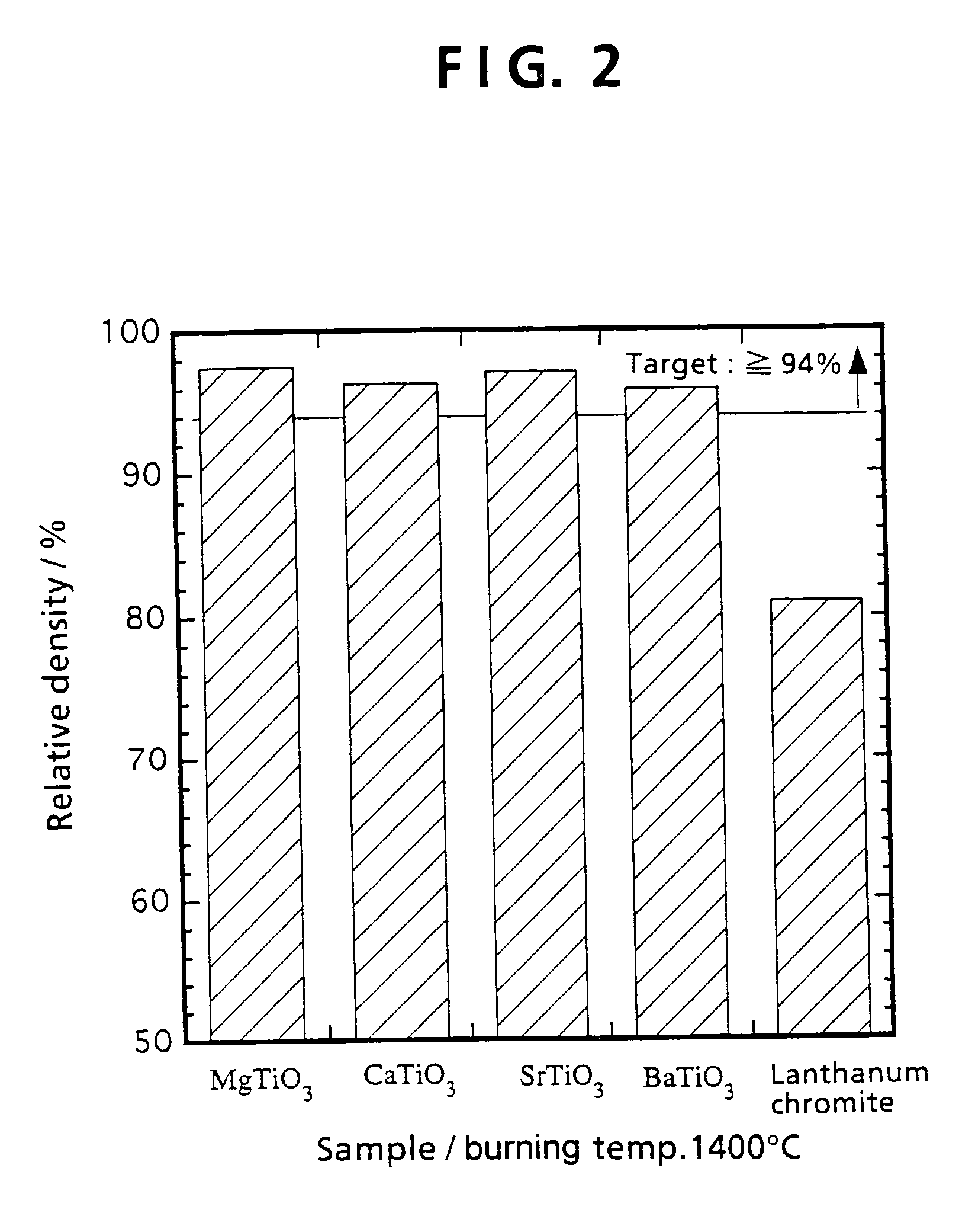
[0123]FIGS. 14 and 15 show the relative densities of burned CaTiO3 system products with the varied amounts of La and Nb added. FIGS. 14 and 15 reveal that even after burning at 1,400° C., the relativ...


PUM


Abstract

A solid electrolyte type fuel battery in which a material for an interconnector for connecting cells of the solid electrolyte type fuel battery comprises a matrix of the general formula MTiO3, where M is an alkaline earth metal element such as Mg, Ca, Sr or Ba. This fuel battery can be produced by burning at a lower temperature of 1,300 to 1,400° C. than before, shows output performance comparable to or better than that of conventional devices, and has better durability and thermo cycle resistance characteristics than the conventional devices.

Description

BACKGROUND OF THE INVENTION[0001]This invention relates to a solid electrolyte type fuel battery.[0002]A fuel battery converts chemical energy, obtained by the reaction between a fuel (a reducing agent) and air (an oxidizing agent), directly into electric energy, rather than taking it as heat. The fuel battery can serve as a highly efficient power generation system, because it carries out direct power generation and it is not restricted by the Carnot's cycle. The fuel battery comes in various types, and can be roughly divided into a phosphate type, a molten carbonate type, and a solid electrolyte type according to the solid electrolyte used. The temperatures used for these types are about 200° C., 600° C. and 1,000° C., respectively. The solid electrolyte type fuel battery, in particular, can utilize high waste heat, and thus shows a high thermal efficiency of about 60%.[0003]The constituent materials for the solid electrolyte type fuel battery, as a single cell, are a solid electro...

Claims


Application Information

Patent Timeline
IPC IPC(8): H01M8/12H01M8/02H01M8/04H01M8/24
CPCH01M8/0215H01M8/2425H01M8/0217Y02E60/50H01M8/2428Y02P70/50H01M8/2404
Inventor NISHI, TOSHIROMURAKAMI, NOBUAKIYAMAMOTO, HIROKAZU
Owner MITSUBISHI HITACHIPOWER SYST LTD
Why Eureka
Try Eureka