Line driver for digital signal transmission

a digital signal and driver technology, applied in repeater/relay circuits, baseband system details, current supply arrangements, etc., can solve the problems of insufficient linearity and speed or bandwidth, insufficient linearity of audio frequency domain transfer characteristics, and distortions in radio frequency range, so as to achieve high linearity in the dc voltage range, high loop gain, and high linearity

Inactive Publication Date: 2006-10-24
INFINEON TECH AG
View PDF8 Cites 2 Cited by
  • Summary
  • Abstract
  • Description
  • Claims
  • Application Information

AI Technical Summary

Benefits of technology

[0019]On account of the feedback with simultaneously high loop gain and the use of resistors, the inventive line driver has a high linearity in the DC voltage range. Similarly, a high linearity is obtained in the radio frequency domain on account of a very high bandwidth for the inventive line driver and effectively reduced parasites in the signal path. The use of current mode technology allows a good signal-to-noise ratio. In addition, the circuit topology of the inventive line driver is relatively easy to align with different standard

Problems solved by technology

A simple connecting wire between the circuits is no longer sufficient in this case.
Particularly when cable lengths vary, it is difficult to meet high demands on the linearity and speed or bandwidth while simultaneously observing the pulse masks of the standard used.
The fundamental drawbacks of these line drivers are inadequate linearity of the transfer characteristic in the audio frequency domain and distortions in the radio frequency range.
The Miller compensations reduce the bandwidth of the amplifier, as a result of which the distortions in the radio frequency signal are caused.
If these line drivers are essentially based on current mirror designs, inadequate linearities are the result.
In addition, the line drivers frequently have a low input resistance, which causes an increased fault current both in the audio frequency signal domain

Method used


Image

  • Line driver for digital signal transmission
  • Line driver for digital signal transmission
  • Line driver for digital signal transmission

Examples


Embodiment Construction

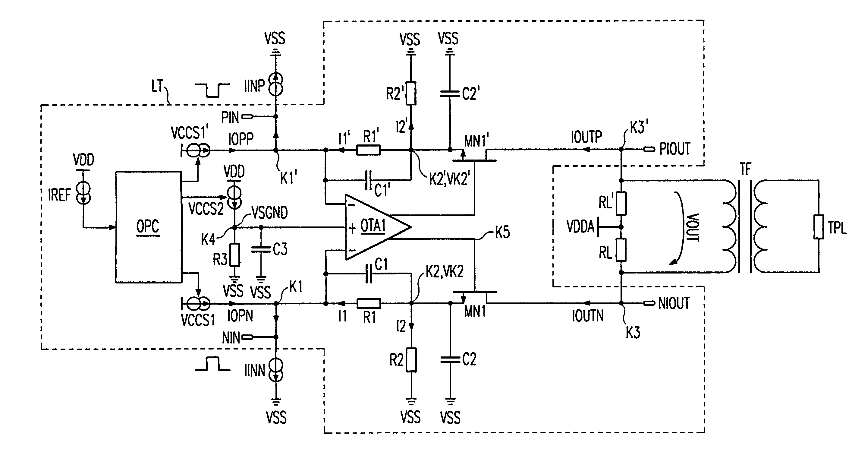
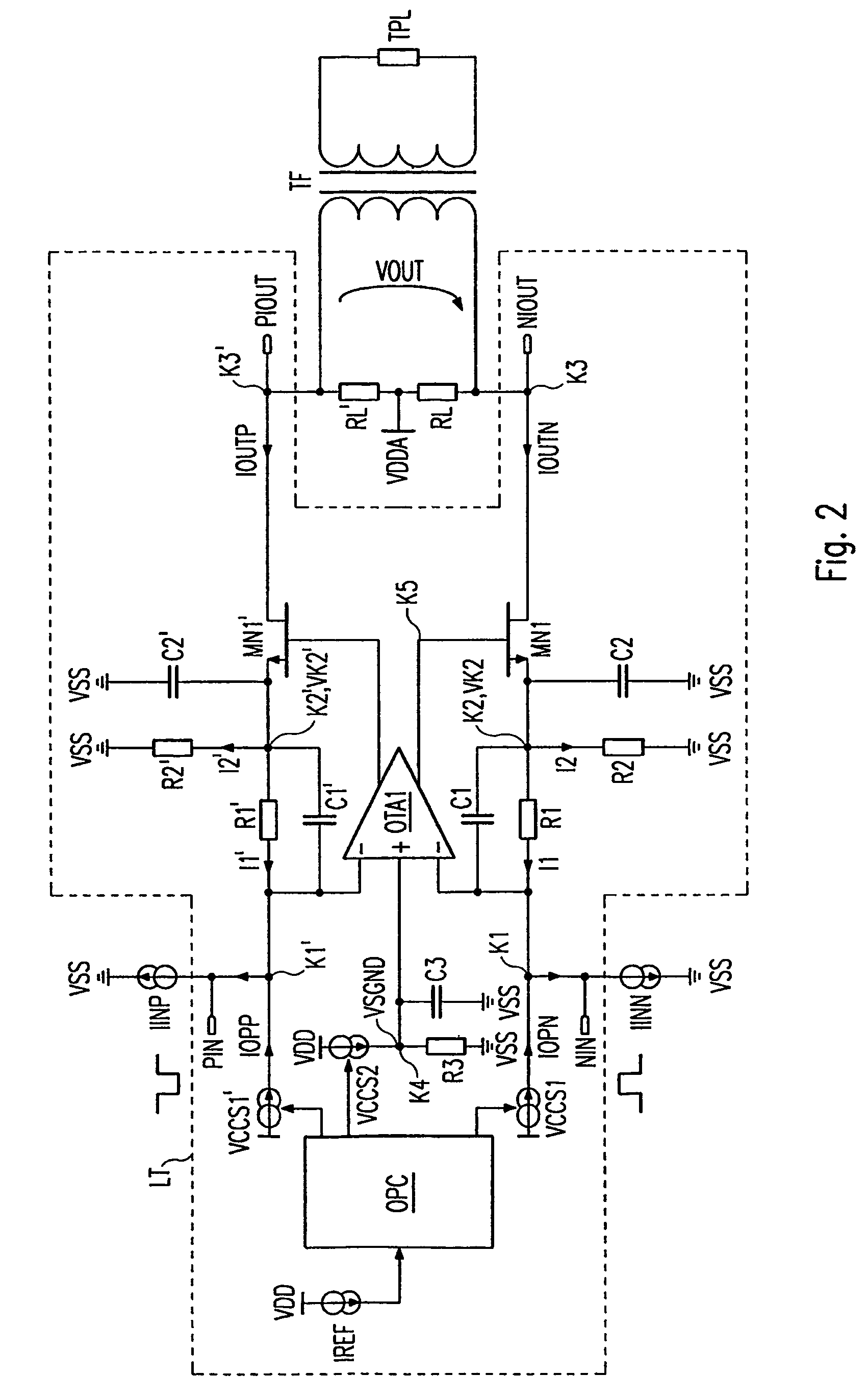
[0043]FIG. 2 shows a circuit diagram of a first exemplary embodiment of an inventive pseudo-differential line driver LT produced using CMOS technology. The circuit diagram of the pseudo-differential line driver LT is arranged symmetrically around a line which is imagined to run horizontally through the center of the circuit diagram. For reasons of simplicity and clarity, the subsequent description of the circuit diagram discusses only the bottom half of the circuit diagram in some cases. Since the symmetry of the circuit diagram is obvious, the way in which the top half of the circuit diagram is connected up and works is obtained in a similar manner. In addition, the designations MNx and MPx (where x=1, 2, 3, . . . ) represent n-channel MOSFETs and p-channel MOSFETs, respectively, below.

[0044]The pseudo-differential line driver LT is in the form of a controllable current source. Complementary input currents IINN and IINP, which feed the pseudo-differential line driver LT at inputs N...


PUM


Abstract

In a line driver an input current (IINN) feeds a node (K1) which is connected to an input on an amplifier (OTA1). A further input on the amplifier (OTA1) has a reference voltage (VSGND) applied to it. The amplifier (OTA1) controls a current source (MN1) which outputs an output current (IOUTN). A current/voltage converter (R1) is connected between the node (K1) and the current source (MN1). A voltage/current converter (R2) is connected between the current source (MN1) and a ground (VSS).

Description

CROSS REFERENCE TO RELATED APPLICATION[0001]This application is a continuation of copending International Application No. PCT / DE02 / 02090 filed Jun. 7, 2002 which designates the United States, and claims priority to German application DE101 35 113.5 filed Jul. 19, 2001.TECHNICAL FIELD OF THE INVENTION[0002]The invention relates to a line driver. In particular, the invention relates to a pseudo-differential line driver for digital signal transmission.DESCRIPTION OF THE RELATED ART[0003]To transmit digital signals from one integrated circuit to a further integrated circuit without corruption, it is necessary to ensure that the connecting lines do not impair the signals. The influence of the connecting lines is not negligible if, for steep signal edges, the propagation time through the connecting lines is at least in the order of magnitude of the circuit's rise time. A simple connecting wire between the circuits is no longer sufficient in this case. To avoid serious signal deformations,...

Claims


Application Information

Patent Timeline
IPC IPC(8): H04M19/00H03F3/45H04L25/02H04L25/20H04M1/00H04M3/00
CPCH04L25/0266
Inventor GREGORIUS, PETER
Owner INFINEON TECH AG
Why Eureka
Try Eureka