Optical transmission system of radio signal over optical fiber link

Inactive Publication Date: 2006-10-24
OKI ELECTRIC IND CO LTD
View PDF6 Cites 108 Cited by
  • Summary
  • Abstract
  • Description
  • Claims
  • Application Information

AI Technical Summary

Benefits of technology

[0019]By constituting the optical transmission system out of the control station and the base stations, and receiving an optical signal transmitted from the control station to the optical fiber using the amplifier-converter which comprises the semiconductor optical amplifier and the electro-absorption modulator at the base station, it is possible to directly connect the base stations to the optical fiber without using optical couplers and perform optical-to-electrical conversion. Due to this, even if the number of base stations increases, the optical power is maintained to facilitate the dependent-connection of the base stations. In addition, the amplification function of the amplifier-converter enables transmitting equal optical power from all the base stations. Thus, it is possible to obtain an optical transmission system for a down link wherein even if a base station is added halfway along the optical fiber, the other base stations are no

Problems solved by technology

However, it is difficult to realize long-distance signal transmission because of the high attenuation of signals in space.
In this case, if the number of base stations increases, the optical power which can be delivered to each bas

Method used


Image

  • Optical transmission system of radio signal over optical fiber link
  • Optical transmission system of radio signal over optical fiber link
  • Optical transmission system of radio signal over optical fiber link

Examples


Example

First Embodiment

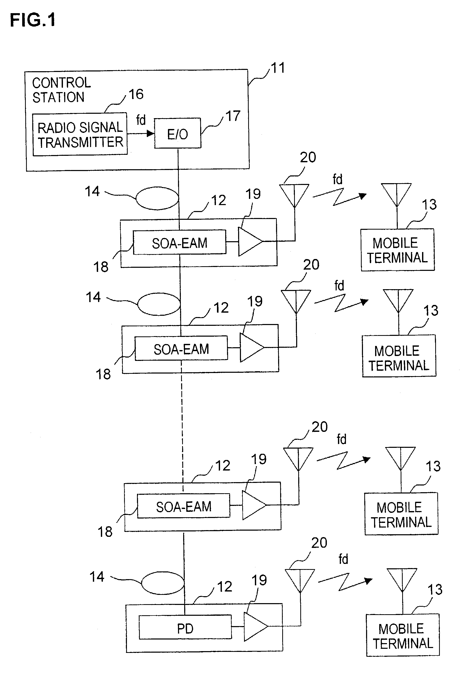
[0028]FIG. 1 is a block diagram of an optical transmission system of a radio signal over an optical fiber link in the first embodiment according to the present invention. As shown in FIG. 1, in the optical transmission system for a down link, a control station 11 comprises a radio signal transmitter 16 and an electrical-to-optical converter (E / O converter) 17. At the control station, a radio signal with a frequency fd is converted to an optical signal by the E / O converter 17, and output to an optical fiber 14. A plurality of (n) radio base stations 12 are dependently connected to the control station 11 using the optical fiber 14.

[0029]Each radio base station 12 comprises an SOA-EAM 18, which is an amplifier-converter comprising a semiconductor optical amplifier (SOA), and an electro-absorption modulator (EAM), a radio signal amplifier (RF-AMP) 19 and an antenna 20.

[0030]The SOA-EAM 18 is constituted to provide the EAM in rear of the SOA and is used as an optical-to-e...

Example

Second Embodiment

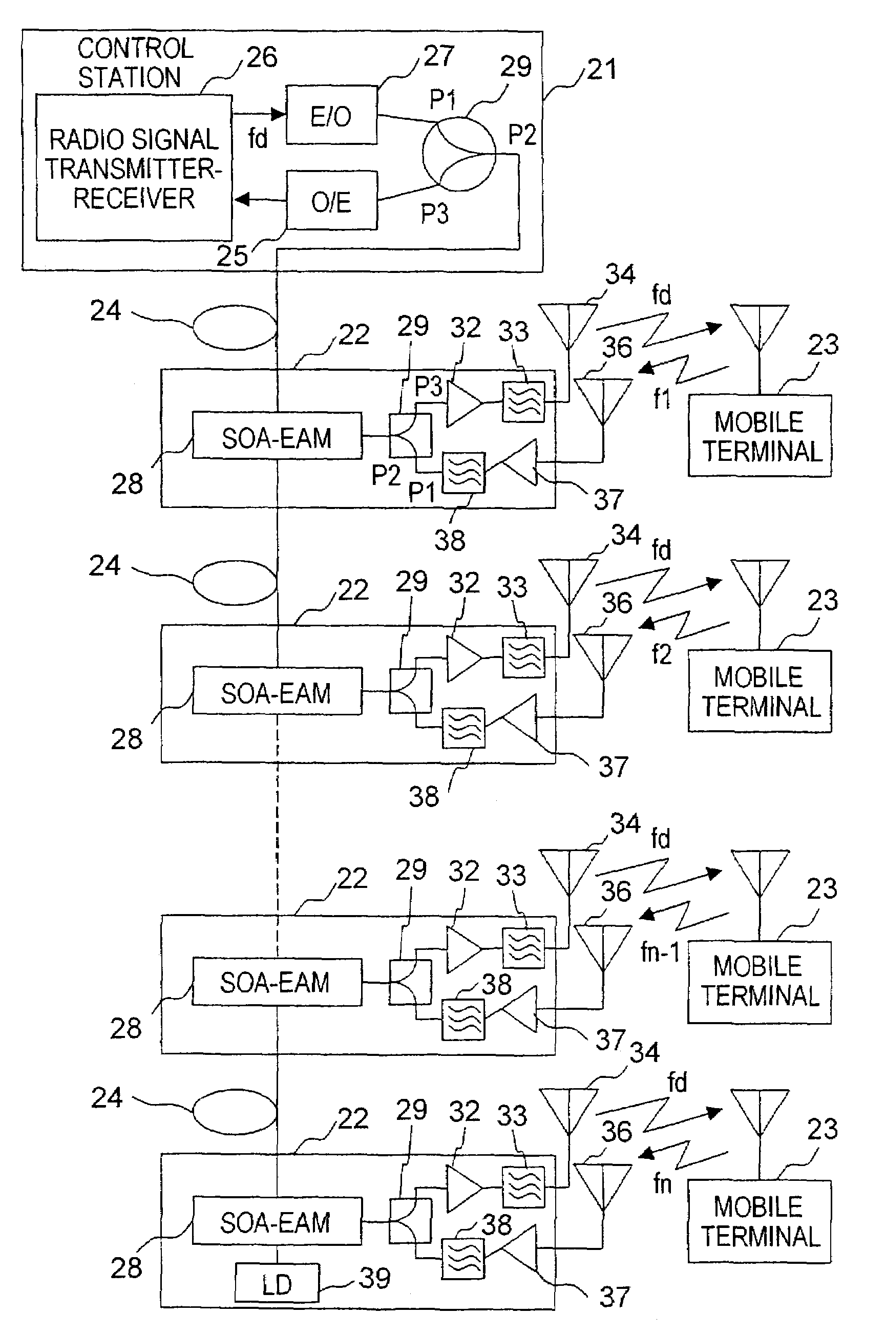
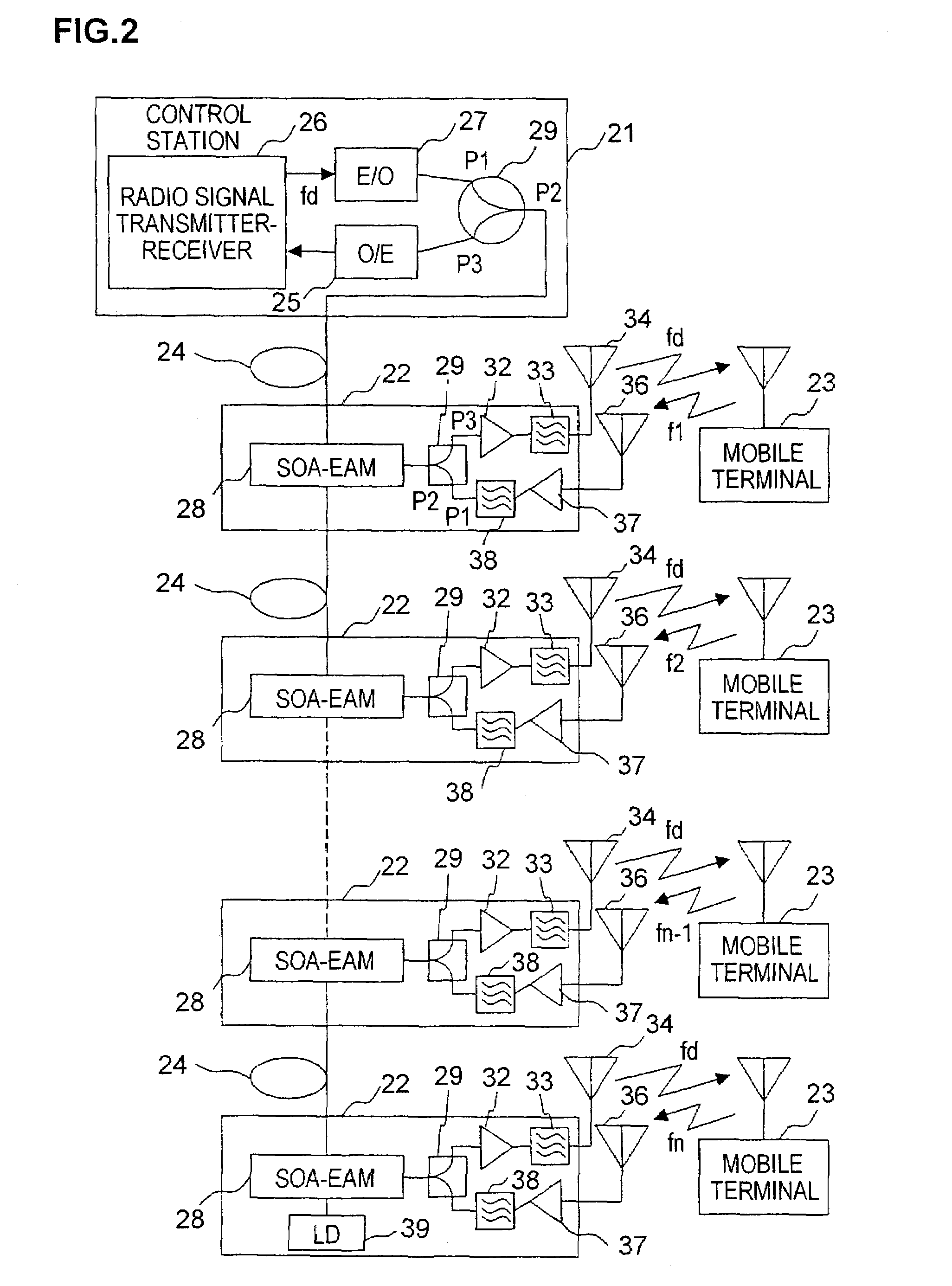
[0037]FIG. 2 is a block diagram of an optical transmission system of a radio signal over an optical fiber link in the second embodiment according to the present invention. As shown in FIG. 2, in an optical transmission system for up and down links in this embodiment, means for dividing transmission time to up transmission time and down transmission time is used, whereby it is possible to transmit signals over up and down links using one optical fiber. Specifically, a control station 21 controls a radio signal transmitter-receiver 26 and an electrical-to-optical converter (E / O converter) 25 comprised therein, as well as an up link signal laser diode (LD) 39 which is provided at a terminal base station 22, and divides transmission time to up and down transmission time in a preset cycle. However, if it is necessary to transmit a transmission signal while adding the control signal of the LD 39 of the terminal base station 22 remote from the control station 21 and if a s...

Example

Third Embodiment

[0048]FIG. 3 is a block diagram of an optical transmission system of a radio signal over an optical fiber link in the third embodiment according to the present invention. In this embodiment, a ring-like optical fiber link, as well as means for dividing transmission time to up transmission time and down transmission time as described above the second embodiment, are provided in the optical transmission system for up and down links. As shown in FIG. 3, a control station 51 comprises a radio signal transmitter-receiver 56, an electrical-to-optical converter (E / O converter) 57 for a down link, an optical-to-electrical converter (O / E converter) 55 for an up link, an optical circulator 59 separating an up optical signal from a down optical signal, and an LD 69 for the up link.

[0049]As in the case of the first embodiment, at down transmission time, on the down link, a radio signal with a frequency fd is converted to an optical signal by the E / O converter 57, passed from the...


PUM


Abstract

In coupling a control station transmitting a radio signal to a plurality of base stations each transmitting the radio signal to a terminal station by an optical fiber, and dependently connecting the plurality of base stations to the optical fiber, the control station includes a radio signal transmitter and an electrical-to-optical converter. Each of the base stations including an SOA-EAM comprises a semiconductor optical amplifier (SOA) and an electro-absorption modulator (EAM), a down link radio signal amplifier, and a down link antenna, the SOA-EAM receiving an optical signal from the control station. The optical transmission system can prevent optical power from lowering even if the number of base stations increases and can facilitate adding a base station since an optical coupler is not used.

Description

BACKGROUND OF THE INVENTION[0001]1. Field of the Invention[0002]The present invention relates to an optical transmission system with a radio technique merged with an optical communication technique, using an optical fiber line between a control station which transmits a radio signal to a plurality of base stations and the base stations which transmit the radio signal to terminal stations. This application is a counterpart application of Japanese application Serial Number 186518 / 2002, filed Jun. 26, 2002, the subject matter of which is incorporated herein by reference.[0003]2. Description of the Related Art[0004]As the optical transmission system with the radio technique merged with the optical transmission technique, the following are well known:[0005]Tsukamoto et al., “Current Activities and Future Trends in Radio-over-Fiber Network”, Journal of IEICE (Institute of Electronics, Information and Communication Engineers), Vol. 80, No. 8, pp. 859–868, August 1997; and[0006]Tarusawa et ...

Claims


Application Information

Patent Timeline
IPC IPC(8): H04B10/00H04B10/2513H04B10/2575H04B10/278H04W92/00H04W92/12H04W92/20
CPCH04B10/25755H04B10/25758
Inventor SASAKI, KENSUKE
Owner OKI ELECTRIC IND CO LTD
Why Eureka
Try Eureka