However, when these conditions are not present, image defects may be introduced due to failures in the capture or
reproduction system, thereby reducing the quality of the final viewed image.
Unfortunately, these features often solve the
primary problem, but add a secondary, sometimes severe, image defect.
However, even if the primary subject now receives adequate illumination, the flash may introduce image defects.
As is well known in the art, the image defect known as redeye may occur when the angle between a narrow
light source, the photographic subject, and the
camera lens is less than approximately three degrees.
The light exits the eye in a narrow cone, and if the
camera lens falls within that cone, the red reflection will be recorded, and may appear in the final image as a red glow in the pupils, which is very undesirable in terms of
image quality.
Redeye is more objectionable when the size of the
pupil in the viewed image is larger and when the red saturation of the
pupil is greater.
While all these methods are efficacious, all have associated disadvantages.
Increased flash-lens separation may lead to more expensive and bulkier cameras and produces more noticeable shadows due to the farther off-axis lighting.
After a preflash is fired, the eye requires half a second or more to respond fully, and during this
delay between the preflash fire and the image capture, facial expressions of the subject often change in an undesirable fashion due to the annoyance and surprise of the preflash.
The preflash also increases camera cost, reduces the power available during the main flash pulse, and increases battery consumption.
Finally, restriction of optical or electronic
zoom factors interferes with the photographer's ability to obtain the desired composition, with the subjects appearing large enough in the image to provide a pleasing rendition.
These digital redeye
removal techniques, while effective, are computationally intensive, and therefore increase the time required to optimally render and reproduce copies of captured images.
The time required to perform these operations may in some cases be the
rate limiting step in automated high speed printing operations.
In addition, if computational time is spent searching for redeye defects in every image, other beneficial
image processing operations such as
tone scale mapping, digital
noise reduction and
sharpening may not be possible in the time interval allocated for each image.
In addition to the redeye image defect, it is well-known that the
physics of
light intensity loss as a function of distance from a narrow source, such as an electronic flash tube, often leads to a defect in lighting contrast and consequently distorted
tone reproduction in the final viewed image.
This defect is particularly detrimental in pictures of people, whose faces are washed out and lack proper
flesh reproduction.
Unfortunately, there is a class of scenes known as backlight that are high in contrast, but have a subject-to-background
exposure ratio that is opposite that of flash scenes.
In this case if the darkening bias needed to correct harsh flash scenes was applied, the already dark primary subject would be rendered even darker, having the effect of further reducing the
image quality.
However, because in both backlight and harsh flash scenes the
dynamic range of the scene may exceed the tonal range of the print material, the primary subject and background can not be simultaneously rendered properly by invoking a full-image-field darken (in the case of harsh flash) or lighten (in the case of backlight) printing correction.
This means that optical (analog) printing systems, which are only capable of producing full-
field exposure corrections, can not produce optimal renditions of
high contrast scenes.
These digital area-specific
tone scale remapping techniques, while effective, are computationally intensive, and therefore increase the time required to optimally render and reproduce copies of captured images.
The time required to perform these operations may in some cases be the
rate limiting step in automated high speed printing operations.
If the
tone scale remapping techniques are applied to every image in a
customer order, even though only a portion of those images actually contain the defect, productivity and profit may be reduced.
In addition, if computational time is spent searching for tone scale defects in every image, other beneficial
image processing operations such as redeye location and correction, digital
noise reduction and
sharpening may not be possible in the time interval allocated for
processing each image.
If the ambient
light level is not sufficient to provide adequate
exposure, and the flash is deactivated or the primary subject is located beyond the maximum flash range, the image capture system will produce an underexposed image.
When processed and printed, images comprised of these fast, large grains permit a reproduction of the scene to be created, but the final viewed image typically contains noticeable
grain structure, which masks fine detail and lowers the perceived image quality.
The appearance of the grain, referred to more generally as
image noise, becomes more objectionable when the reproduction
magnification is increased, for example, in enlargements, pseudo-panoramic or pseudo-telephoto print formats.
When the ambient
light level is low (dim scene), the
amplifier gain is increased, which produces a low (unfavorable) SNR.
When the
gain is increased in this fashion, the
tone reproduction of the image is improved relative to the standard
amplifier gain; however, due to the low SNR, the final viewed image will typically contain noticeable
noise, analogous to the grain in underexposed film images, which masks fine detail and lowers the perceived image quality.
The appearance of noise defects becomes more objectionable when the reproduction
magnification is increased, for example, in enlargements, pseudo-panoramic or pseudo-telephoto (electronic
zoom) print formats.
These digital area-specific
noise reduction techniques, while effective, are computationally intensive, and therefore increase the time required to optimally render and reproduce copies of captured images.
The time required to perform these operations may in some cases be the
rate limiting step in automated high speed printing operations.
In addition, if computational time is spent searching for and correcting noise defects in every image, other beneficial image processing operations such as redeye location and correction, tone scale remapping and
sharpening may not be possible in the time interval allocated for processing each image.
Even if the photographic environment provides ambient light that is uniform and of sufficient intensity to provide an
exposure level that obviates the need for electronic flash or high-noise ambient captures, and the primary subject is within the focus range of the camera, the
camera lens magnification provided by the
normal lens (often defined as the
diagonal dimension of the image capture frame) may be insufficient to capture an image of the primary subject that is the preferred size in the final viewed image.
The increase in AM provided by the aforementioned techniques may lead to a more pleasing composition, however, it also magnifies image blur resulting from inadequate lens depth-of-field, subject motion, and photographer
hand tremor.
The magnified image blur causes sharpness defects to be visible in the final viewed image.
These digital area-specific sharpening techniques, while effective, are computationally intensive, and therefore increase the time required to optimally render and reproduce copies of captured images.
The time required to perform these operations may in some cases be the rate limiting step in automated high speed printing operations.
In addition, if computational time is spent searching for and correcting sharpness defects in every image, other beneficial image processing operations such as redeye location and correction, tone scale remapping and
noise reduction may not be possible in the time interval allocated for processing each image.
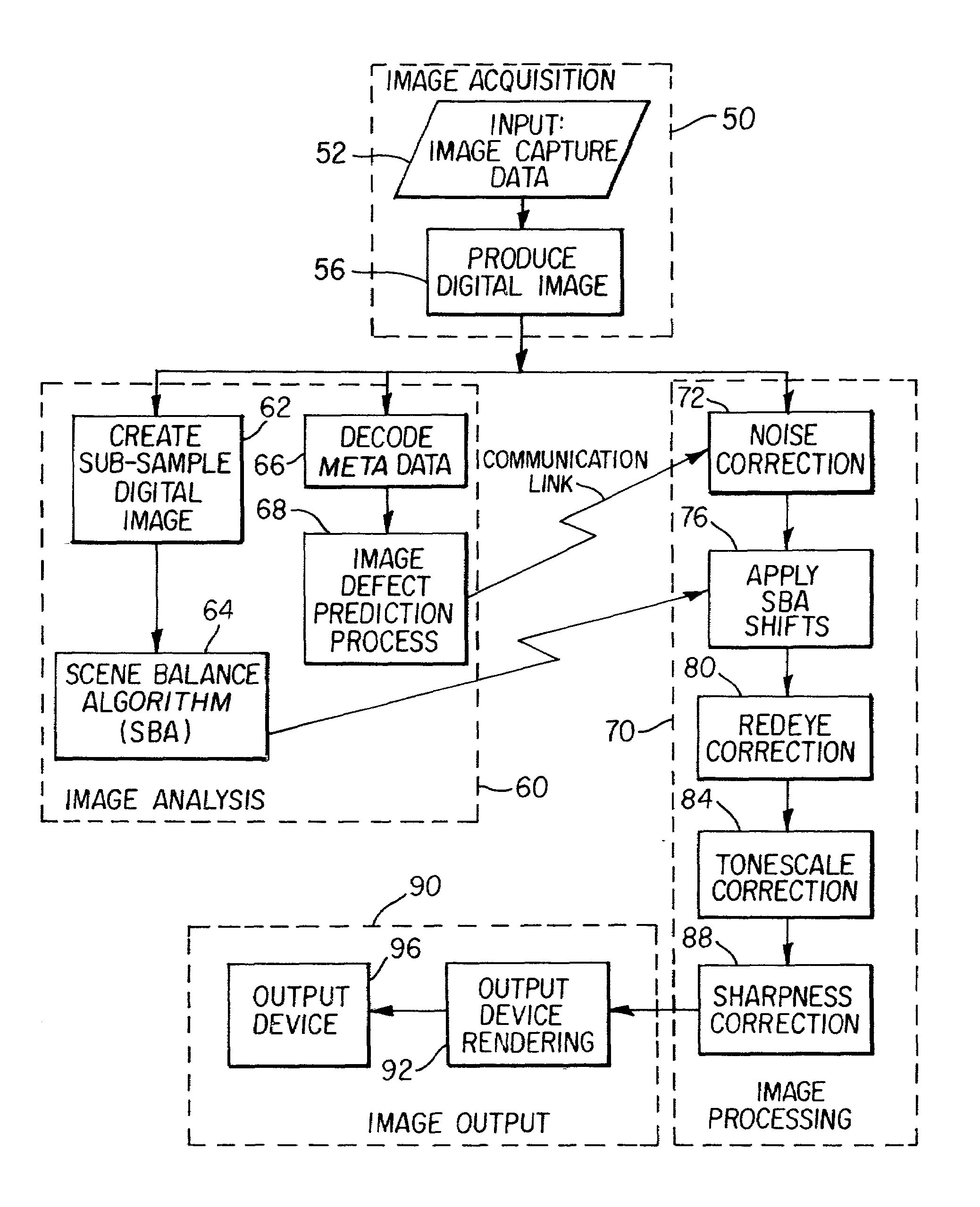
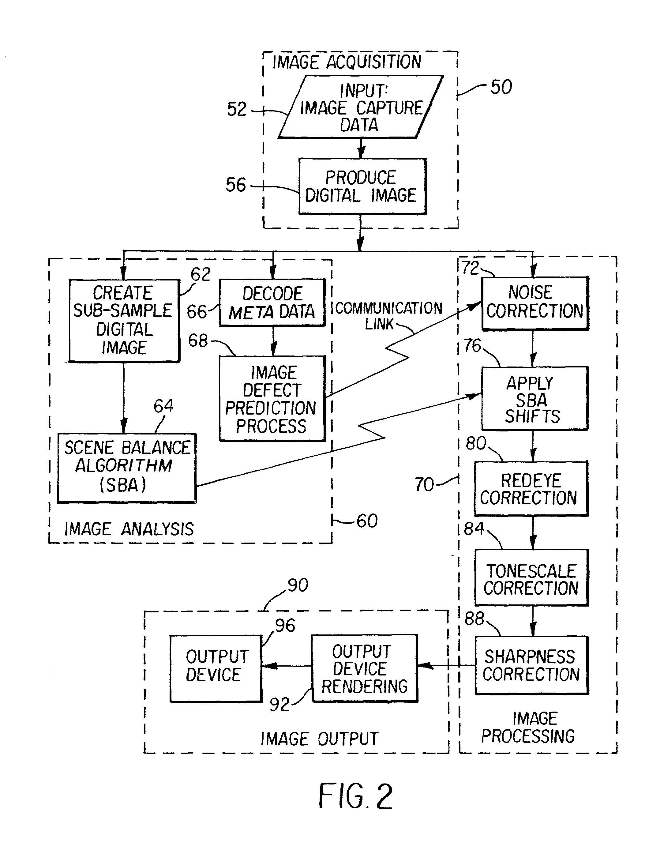
Despite the elaborate methodology disclosed in U.S. Pat. Nos. 5,694,484 and 5,835,627, such systems fail to recognize the importance and use of capture-specific data, that is, variable data collected at the time of image capture, to predict on an image by image basis the best selection of image defect correction algorithms to apply.

