Rapid depth scanning optical imaging device

a depth scanning and optical imaging technology, applied in measurement devices, instruments, interferometers, etc., can solve the problems of difficult to improve a signal-to-noise ratio, poor image quality, and limited frequency of voltage applied to drive the reference mirror so as to advance or withdraw it by about 5 mm, etc., to achieve rapid reference scanning and high signal-to-noise ratio

Inactive Publication Date: 2006-11-07
OLYMPUS CORP
View PDF12 Cites 32 Cited by
  • Summary
  • Abstract
  • Description
  • Claims
  • Application Information

AI Technical Summary

Benefits of technology

[0017]An object of the present invention is to provide an optical imaging device having a rapid reference scanning means that offers a high signal-to-noise ration and enables realization of an inexpensive interferometer.

Problems solved by technology

However, the U.S. Patent Publication No. 5459570 has revealed that since the reference mirror is relatively heavy, the frequency of a voltage to be applied to drive the reference mirror so as to advance or withdraw it by about 5 mm is limited to several tens of hertz.
This discourages diagnosis of a living tissue in that image quality is poor due to blurring deriving from motions including heartbeats.
It is therefore hard to improve a signal-to-noise ratio.
Moreover, 75% of feeble light reflected from a living body is abandoned.
This also degrades the signal-to-noise ratio.
However, this method has a drawback that light detected through heterodyning is also attenuated.
In this case, it is hard to rapidly scan an object in a direction of its depth and observe the object in real time.
The Michelson interferometer has a drawback that an expensive isolator or the like is usually needed to treat light of wavelengths falling outside a wavelength band assigned to optical communication (1.3 or 1.55 μm).
This also deteriorates the signal-to-noise ratio.
Otherwise, since light undergoing little Doppler shift is detected, the efficiency in detection is deteriorated.

Method used


Image

  • Rapid depth scanning optical imaging device
  • Rapid depth scanning optical imaging device
  • Rapid depth scanning optical imaging device

Examples


first embodiment

[0128]

[0129](Constituent Features)

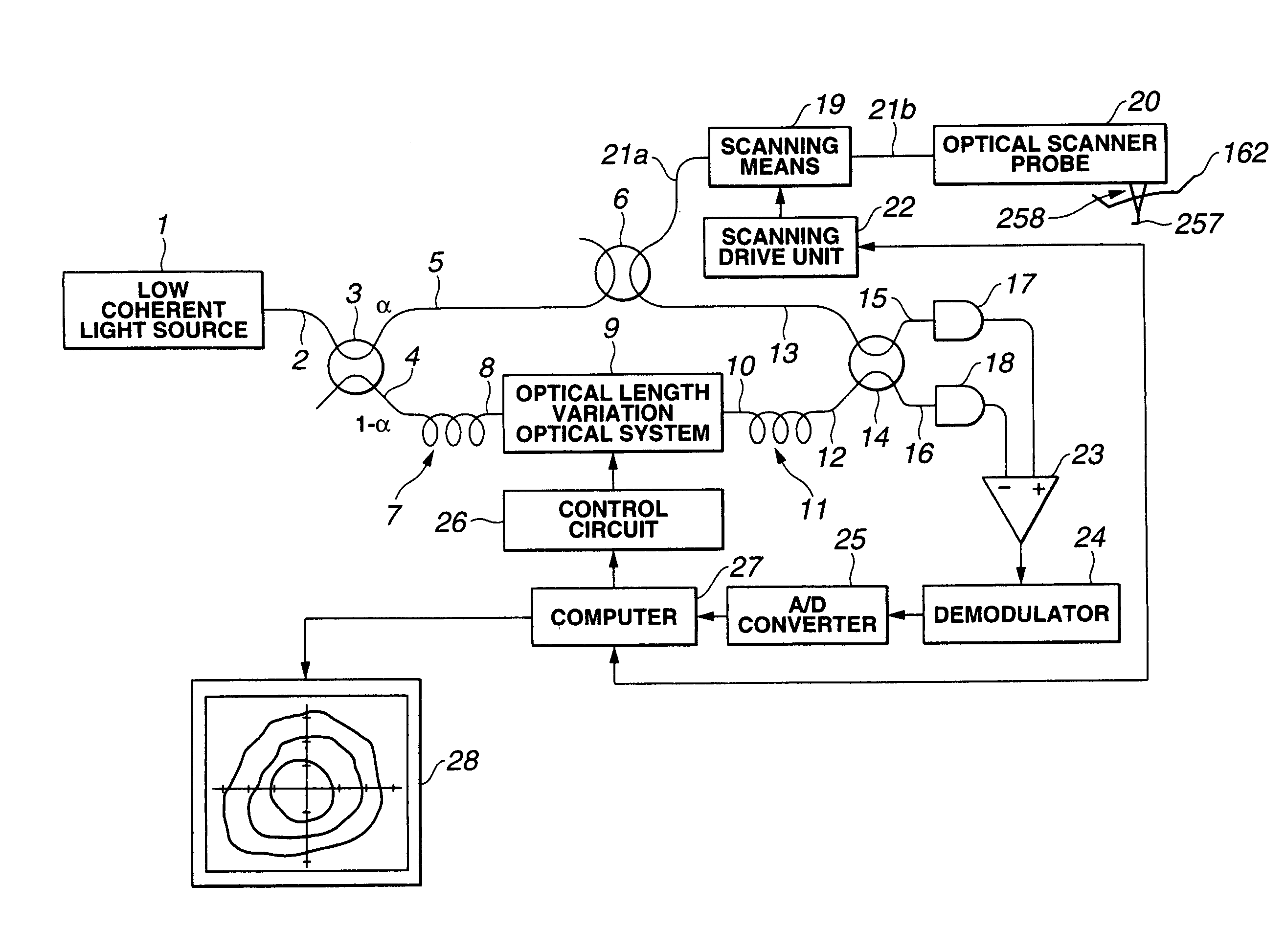
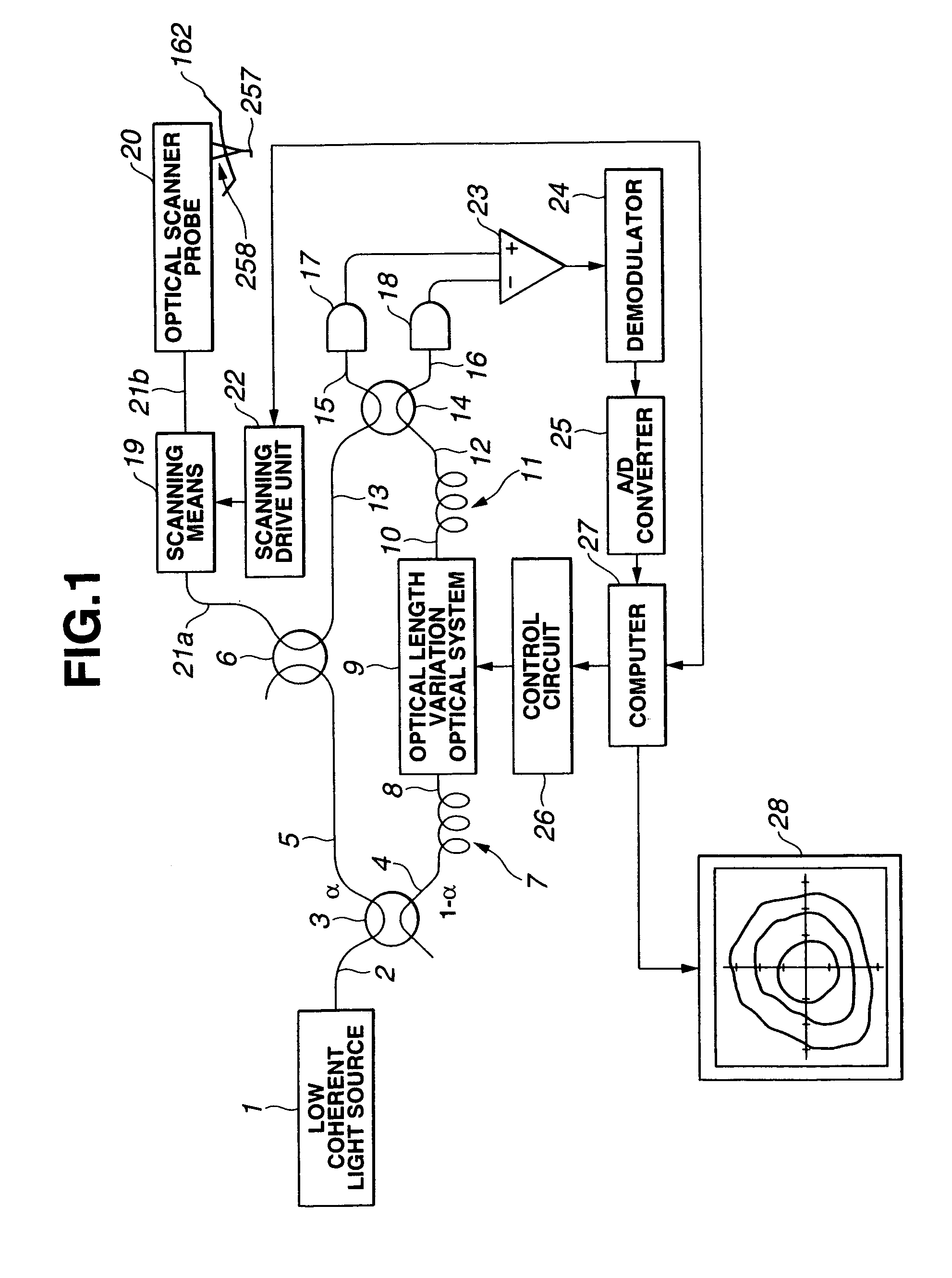
[0130]An optical imaging device shown in FIG. 1 has a low coherent light source 1 such as a super-luminescent diode (SLD). Light emanating from the low coherent light source 1 and having a wavelength of, for example, 1300 nm, requires a coherence length of, for example, about 15 μm, and exhibits low coherence that is of the level of producing interference within only a narrow range on an object. For example, assuming that the light is bifurcated into two light beams and then reunited, only when a difference between the optical lengths for the two beams from the point of bifurcation to the point of reunion is about 15 μm, the beams interfere with each other.

[0131]The light emanating from the low coherent light source 1 is routed to a first single-mode (hereinafter SM) optical fiber 2, and branched into a second SM optical fiber 4 and a third SM optical fiber 5 by an optical coupler 3. The optical coupler 3 branches the light on the first SM optical f...

second embodiment

[0233]

[0234]The second embodiment is a variant of the first embodiment in terms of the optical elements located behind a second diffraction grating included in an optical length variation optical system.

[0235]FIG. 10 schematically shows the arrangement of optical elements located behind a second diffraction grating included in an optical length variation optical system employed in the second embodiment. The optical elements located ahead of the second diffraction grating h8 are identical to those employed in the first embodiment. Illustration of the optical elements will therefore be omitted. Moreover, the other components of a tomographic observation / diagnosis device realized with an optical imaging device in accordance with the present embodiment other than the optical length variation optical system are identical to those of the first embodiment. An overall configuration of an optical coherent tomography system including the optical imaging device will therefore be omitted.

[0236]...

third embodiment

[0251]

[0252]The third embodiment has a wedged prism, which serves as a phase modulation element included in an optical length variation optical system employed in the first embodiment, replaced with another optical element.

[0253]FIG. 15 schematically shows the components of an optical length variation optical system in accordance with the present embodiment. The other components of a tomographic observation / diagnosis device realized with an optical imaging device in accordance with the present invention other than the optical length variation optical system are identical to those of the first embodiment. An overall configuration of an optical coherence tomography system including the optical imaging device will therefore be omitted.

[0254]The optical length variation optical system in accordance with the present embodiment consists mainly of a light introduction block h3, a pair of a first diffraction grating h4 and a first positive lens h5, a prism h6′, a pair of a second positive l...


PUM


Abstract

An optical imaging device includes a reference scanning unit offering a high signal-to-noise ratio and capable of scanning an object rapidly. An interference optical system can be realized inexpensively. In the optical imaging device, low coherent light passed through an optical coupler and another optical coupler, irradiated from an optical scanner probe, reflected from an observed point in a living tissue, returned to the optical coupler, propagated over a fourth SM optical fiber, and routed to another optical coupler shall be referred to as sample light. Light passed through an optical length variation optical system via the optical coupler and routed to the optical coupler shall be referred to as reference light. At this time, a difference between a delay time undergone by the sample light and a delay time undergone by the reference light is proportional to a difference between an optical length for the sample light and an optical length for the reference light. When the optical length difference falls within a coherence length, the sample light and reference light interfere with each other. An interfering signal is acquired into a computer through detectors, a differential amplifier, a demodulator, and an A/D converter.

Description

CROSS-REFERENCE TO RELATED APPLICATION[0001]This application is based on and claims priority to patent application Ser. No. 09 / 656,799, filed Sep. 7, 2000 entitled RAPID DEPTH SCANNTNG OPTICAL IMAGING DEVICE, the entire contents of which are incorporated herein by reference.[0002]This application claims benefit of Japanese Application No. Hei 11-256294 filed in Japan on Sep. 9, 1999, and Japanese Application No. 2000-78743 filed in Japan on Mar. 21, 2000, and Japanese Application No. 2000-154417 filed in Japan on May 22, 2000, the contents of which are incorporated by this reference.BACKGROUND OF THE INVENTION[0003]1. Field of the Invention[0004]The present invention relates to an optical imaging device for irradiating low coherent light to an object, and constructing tomographic images of the object using information-bearing light scattered from the object.[0005]2. Description of the Related Art[0006]In recent years, optical coherent tomography (OCT) for constructing tomographic im...

Claims


Application Information

Patent Timeline
Patent Type & Authority Patents(United States)
IPC IPC(8): G01B9/02
CPCG01B9/0201G01B9/02007G01B9/02003G01B9/0205G01B9/02091G01B2290/70G01B2290/20G01B2290/40G01B2290/65G01B2290/35
Inventor HORII, AKIHIROKANEKO, MAMORUHIRATA, TADASHIMIZUNO, HITOSHI
Owner OLYMPUS CORP
Why Eureka
Try Eureka