Method of manufacturing separator for fuel cell

a technology of fuel cell separator and manufacturing method, which is applied in the direction of cell components, final product manufacturing, sustainable manufacturing/processing, etc., can solve the problems of voltage drop, difficult molding of grooves, and small output of fuel cells

Inactive Publication Date: 2006-11-21
HONDA MOTOR CO LTD
View PDF8 Cites 5 Cited by
  • Summary
  • Abstract
  • Description
  • Claims
  • Application Information

AI Technical Summary

Benefits of technology

[0024]So, in this invention, cooling water passages are formed inside a separator by making a cooling water core with a water-soluble polymer and dissolving the cooling water core with water after the molding of the separator. Because cooling water passag

Problems solved by technology

Also, on one side of the first separator or the second separator gas flow passage grooves must be provided, and on the other side cooling water passage grooves must be provided, and the molding of the grooves becomes difficult.
And also, b

Method used


Image

  • Method of manufacturing separator for fuel cell
  • Method of manufacturing separator for fuel cell
  • Method of manufacturing separator for fuel cell

Examples


first embodiment

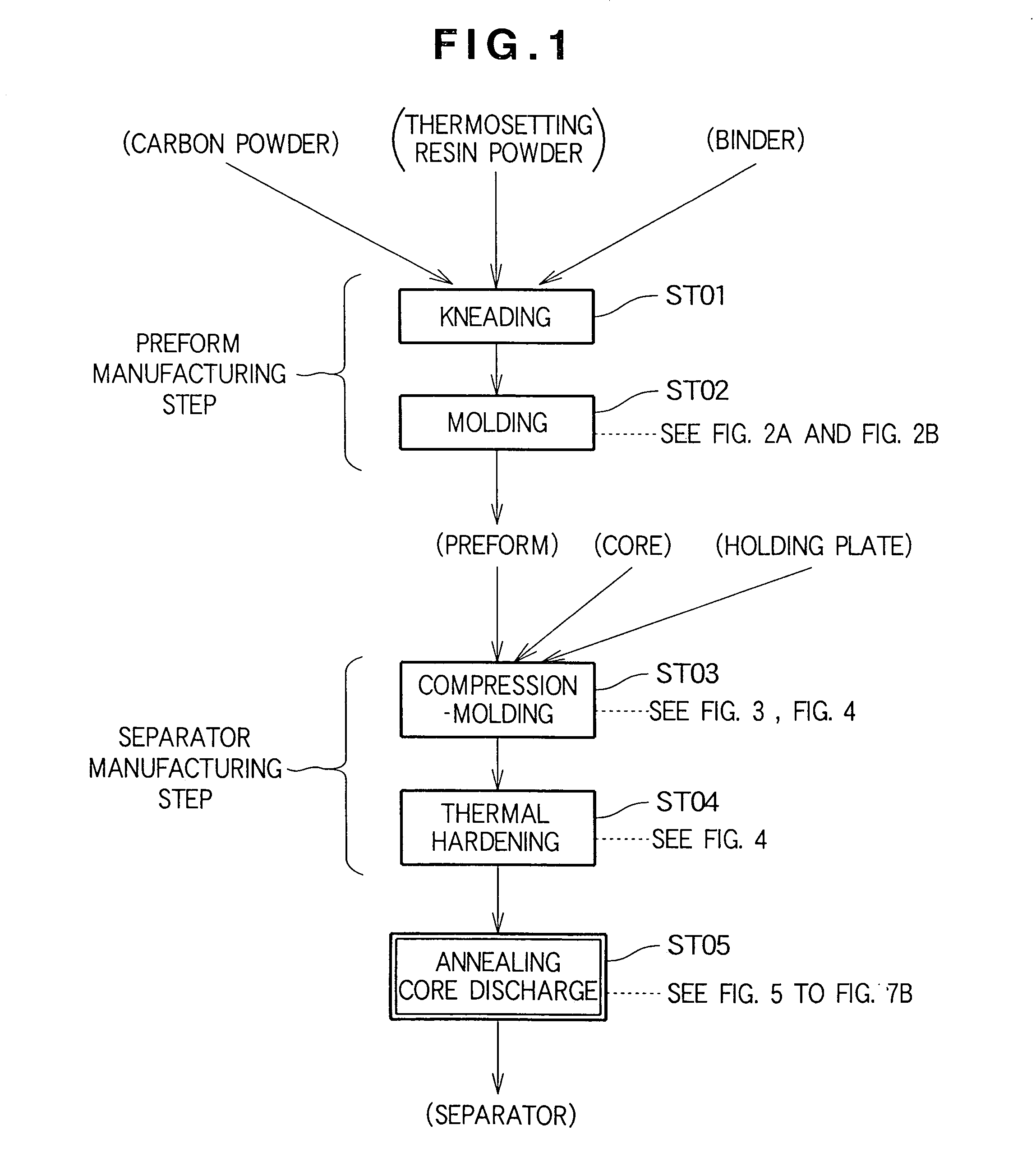
[0052]FIG. 1 shows a manufacturing flow chart of a fuel cell separator according to the invention.

[0053]Step (hereinafter, ST) 01: Carbon powder and thermosetting resin powder are blended in a predetermined blend ratio, a suitable amount of binder is added, and the blend is kneaded.

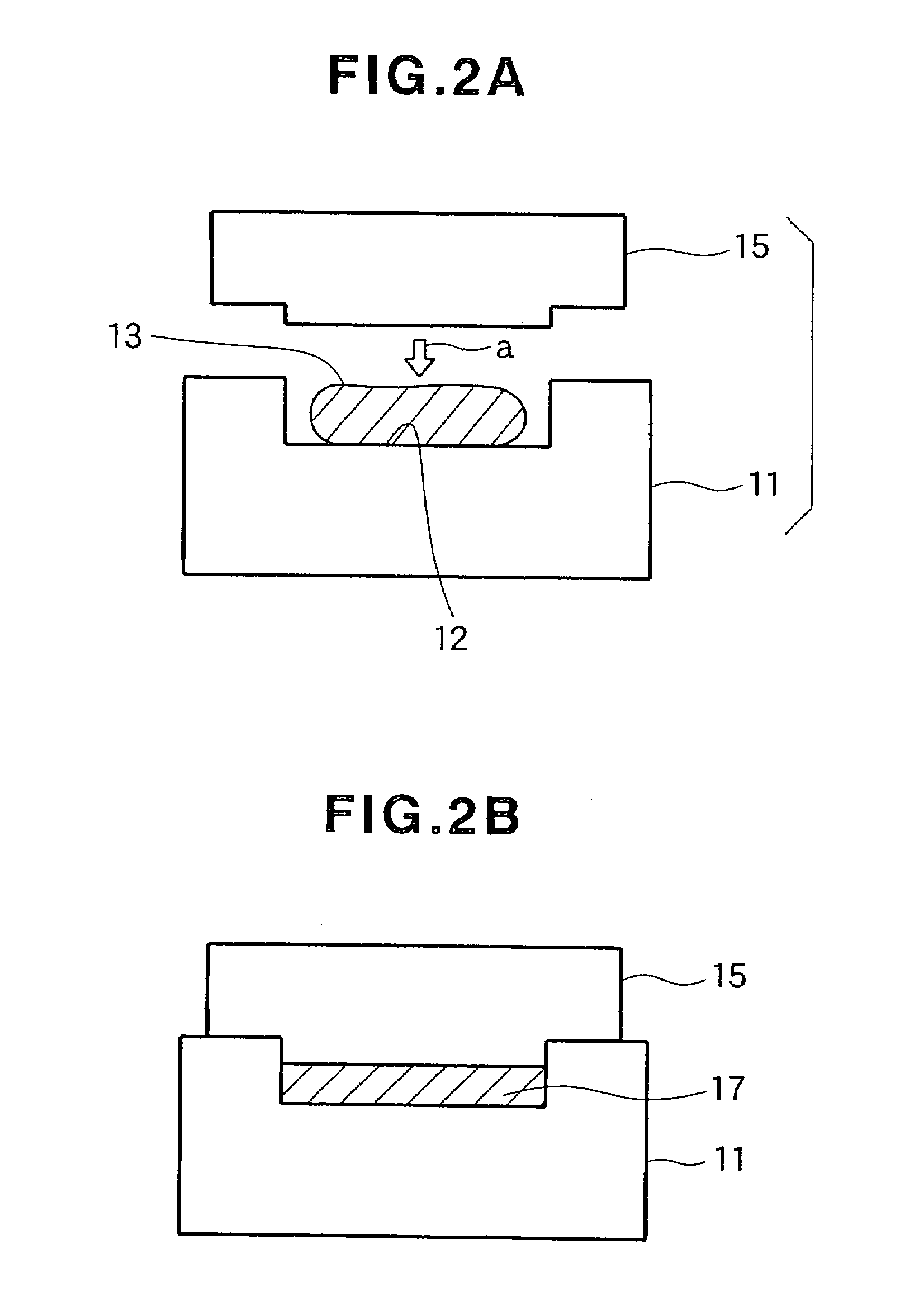
[0054]ST02: A preform is made by molding the kneaded mixture as shown in FIG. 2A and FIG. 2B. First, in FIG. 2A, the knead 13 is placed on a molding face 12 of a lower preform molding die 11. Then, an upper preform molding die 15 is lowered as shown by the arrow a, and the knead 13 is pressure-molded. Next, as shown in FIG. 2B, a preform 17 of a required shape is molded by the lower preform molding die 11 and the upper preform molding die 15.

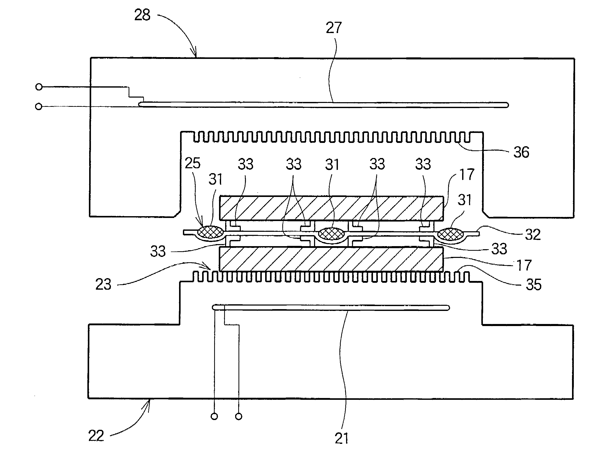
[0055]ST03: A core and a holding plate holding this core are interposed between two of these preforms, and the preforms, core and holding plate are compression-molded en bloc.

[0056]ST04: Substantially simultaneously with the start of this compression molding, a therma...

third embodiment

[0108]Also, in the third embodiment, although an example was shown wherein the cores are heated directly by electricity being passed through them and are discharged with compressed air, the invention is not limited to this, and alternatively the cores may be heated directly by electricity being passed through them and discharged with centrifugal force.

fifth embodiment

[0109]And also, in the fifth embodiment, although an example was shown wherein water passage forming rods constituting cores were embedded in the preform and two of these preforms were compression-molded to mold a separator, the invention is not limited to this, and alternatively water passage forming rods may be interposed directly between two preforms (for example the preform 17 shown in FIG. 2B) and compression-molded en bloc to mold the separator.


PUM

PropertyMeasurementUnit
Solubility (mass)aaaaaaaaaa
Contact resistanceaaaaaaaaaa

Abstract

In manufacturing a separator for use in a fuel cell, first, a core (31, 94) is interposed between two preforms (17, 90, 101) and a with-core separator (41, 95, 107) is formed. After this, the core is melted by heating and discharged to form multiple cooling water passages (54). Because consequently there is no need to bring separators together to form the cooling water passages, a seal becomes unnecessary. Also, since there is no need to bring separators together the electrical contact resistance also falls.

Description

TECHNICAL FIELD[0001]This invention relates to a method for manufacturing a fuel cell separator for constituting a cell module by appending an anode side electrode and a cathode side electrode to an electrolyte film and sandwiching these from both sides.BACKGROUND ART[0002]A fuel cell utilizes a principle opposite the water electrolysis to generate electricity by causing hydrogen and airborne oxygen to chemically react. Theoretically, the only emission is water. Generally, hydrogen is used as the fuel gas and air or an oxidant gas is used as the oxygen.[0003]As a fuel cell of this kind, for example the “fuel cell” disclosed in Japanese Patent Laid-Open Publication No. 2000-123848 is known. This fuel cell has a structure wherein a cell module is constructed by sandwiching an electrolyte film with an anode electrode and a cathode electrode and sandwiching the outer side faces of the anode electrode and the cathode electrode with a first separator and a second separator respectively by...

Claims


Application Information

Patent Timeline
IPC IPC(8): H01M2/00H01M2/14H01M2/16B29C43/02B29C43/20B29C43/36H01M8/02H01M8/04
CPCB29C43/021B29C43/203B29C43/36H01M8/0226H01M8/0267H01M8/04074B29C2043/023B29C2043/3665B29C2043/3668B29K2503/04B29L2031/3468H01M8/0213H01M8/0221H01M8/04029Y02E60/50H01M8/0263H01M8/2483Y02P70/50H01M8/02H01M8/0258
Inventor YOSHIDA, TAKASHIISHIGURO, KENICHINISHI, YOSHITSUGU
Owner HONDA MOTOR CO LTD
Why Eureka
Try Eureka