Method of checking the layout versus the schematic of multi-fingered MOS transistor layouts using a sub-circuit based extraction

a multi-fingered mos transistor and layout technology, applied in the field of very large-scale integrated circuit (vlsi) chip design, can solve the problems of inability to achieve a conventional flat extraction method, two electrically equivalent child cells may be matched inappropriately, and the performance of the circuit being manufactured may deviate significantly from the design target specifications, etc., to achieve meaningful and understandable extraction netlist, accurate verification and simulation, and the effect of reducing the number of parasitic devices

Inactive Publication Date: 2006-11-21
IBM CORP
View PDF10 Cites 30 Cited by
  • Summary
  • Abstract
  • Description
  • Claims
  • Application Information

AI Technical Summary

Benefits of technology

[0026]Accordingly, it is an object of the invention to perform an IC layout extraction using an improved sub-circuit method so that all the device geometric parameters can be properly and completely extracted.
[0027]It is another object to perform a layout versus schematic comparison based on the improved sub-circuit extraction method so that the LVS is complete and accurate to satisfy the high confidence level required for physical verification in an advanced IC design.
[0031]In another aspect of the invention, the algorithm treats each FET as a sub-circuit and not as a flat MOSFET device and the sub-circuit based netlist resembles a schematic netlist. This is critical for passing many parameters (i.e., the number of fingers, drain and source diffusion geometries, local statistics, etc.) needed by the netlister / simulator for a downstream simulation and analysis. It also includes all the device properties in the extraction and comparison which translates into a more accurate verification and simulation.
[0032]Finally, the parasitic device extraction and post-layout simulation (360 in FIG. 3) accuracy also benefits from the disclosed algorithm. Because this invention yields a more meaningful and understandable extracted netlist, parasitic device extraction can be performed more efficiently and accurately. The majority of the parasitic extraction task focuses on the extrinsic parasitics (i.e., the wiring and substrate effects, etc.) which depend on the device interconnects, while leaving the intrinsic parasitics (i.e., the gate resistance, contact resistance, junction capacitance, etc.) to be handled by the sub-circuit models. This leads to a fast and accurate post-layout simulation downstream while making it easier to identify how interconnect or device related layout impacts circuit performance.

Problems solved by technology

The performance of the circuit being manufactured may deviate significantly from the design target specifications because differences between the physical layout and the circuit schematic are not fully checked.
This cannot be achieved by way of a conventional flat extraction method.
However, two electrically equivalent child cells may be matched inappropriately if the detailed cell attributes are not fully extracted and compared.
This results in the transistors shown in FIGS. 5a–5b to be successfully matched to an identical schematic cell inappropriately because it is based on a presumption that the two transistors, i.e., FIG. 5a and 5b match each other, which, is incorrect.
Although flat MOS transistor modeling has been used for many decades and it is known that it runs the fastest, it lacks the flexibility and accuracy of a parameterized sub-circuit modeling.
However, the sub-circuit described in the combined publications is a combination of several MOS transistors and / or resistors, etc., but not a transistor level representation that can be used to improve the geometric property comparison accuracy.
Moreover, it is not possible to compare additional device features such as diffusion segment dimensions, which typically have a significant impact on the device and circuit performance.
In addition to breaking the design coherence with the schematic by recognizing a single device as multiple primitive elements, this practice leads to simulation inefficiencies downstream requiring an iterative solution of multiple elements instead of a single sub-circuit device model.
This practice only partially works for a multi-finger layout because the critical device property “number of fingers” cannot be checked.
Known solutions cannot extract a complete list of geometric parameters of a transistor and perform a complete parametric and connectivity verification.

Method used


Image

  • Method of checking the layout versus the schematic of multi-fingered MOS transistor layouts using a sub-circuit based extraction
  • Method of checking the layout versus the schematic of multi-fingered MOS transistor layouts using a sub-circuit based extraction
  • Method of checking the layout versus the schematic of multi-fingered MOS transistor layouts using a sub-circuit based extraction

Examples


Embodiment Construction

[0042]The invention will now be described first by way of extracting all the geometric parameters of a MOS transistor layout to be followed by a description of performing the sub-circuit based layout versus schematic comparison.

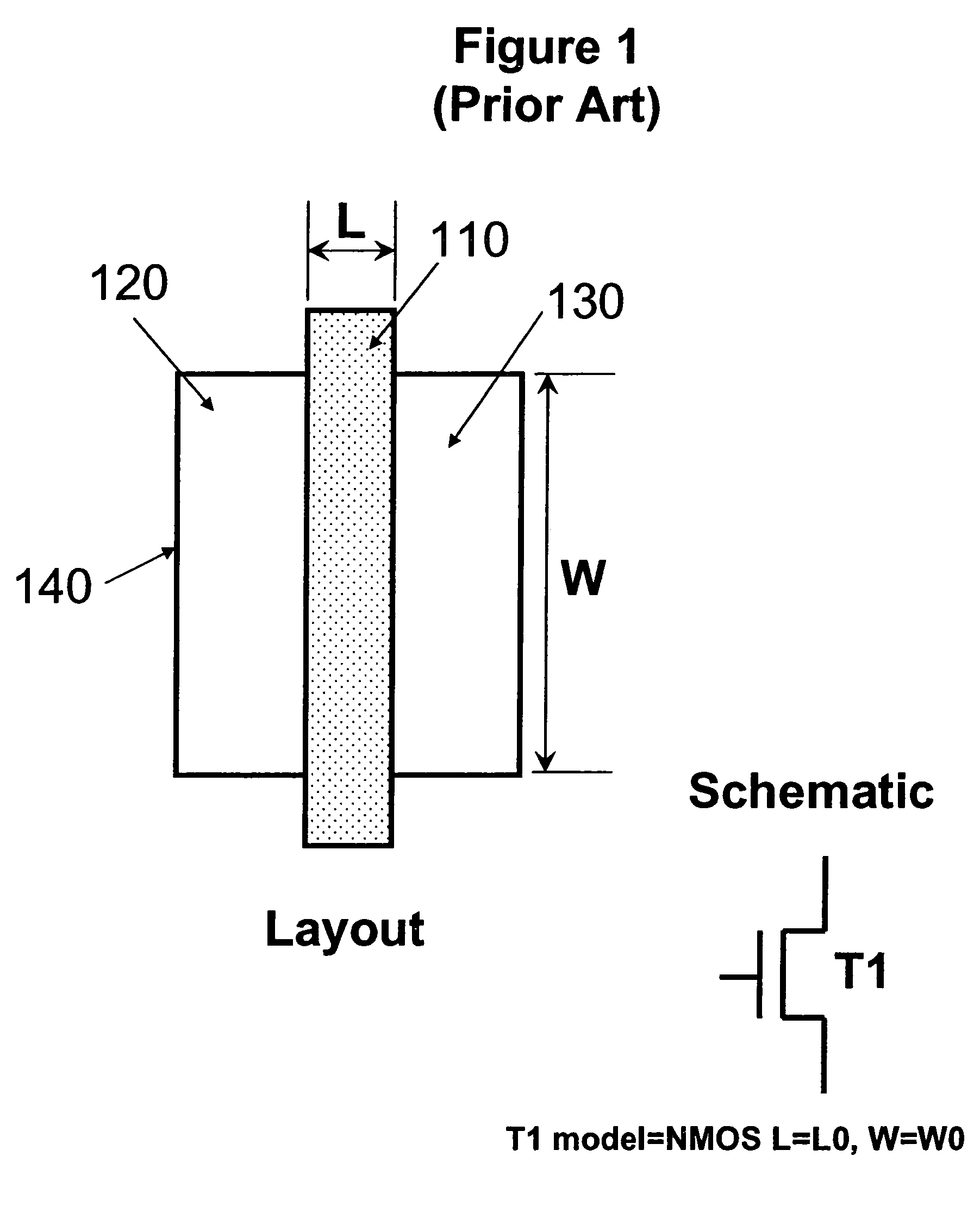
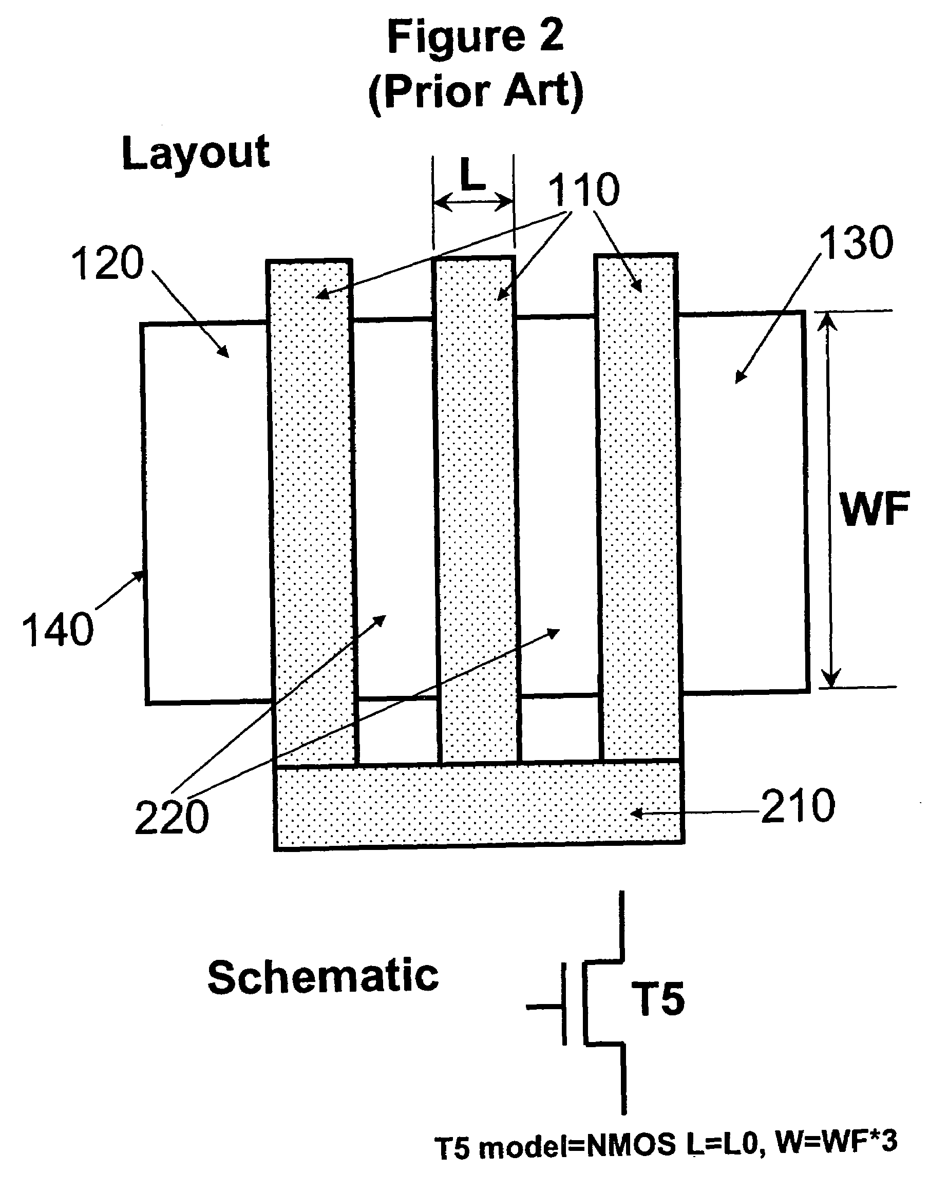
[0043]The main thrust of the invention is to extract the multi-fingered MOS transistor as one sub-circuit entity with all the geometric parameters such as the channel length and width, number of fingers, source and drain diffusion dimensions, and appropriate node connections included in the extracted netlist. To illustrate the inner workings of the invention, a parameterized sub-circuit MOS transistor with multi-finger layout is shown in FIG. 4. The geometric parameters are channel length “L”, channel width per finger “WF”, number of fingers “NF” (number count of 110s), left-side diffusion dimension “DIFFL”, right-side diffusion dimension “DIFFR”, and middle diffusion dimension “DIFFM”. The parameters “L”, “WF”, and “NF” are the same as those of a flat MOS tr...


PUM


Abstract

A sub-circuit based extraction method which extracts a multi-finger MOS transistor directly as a sub-circuit is described. By adding three marking layers, the method provides the layout extracted netlist with a complete list of device geometric parameters corresponding to the device properties as presented in the sub-circuit model based schematic netlist. By performing a layout-versus-schematic comparison based on all geometric parameters extracted, the layout checking is performed in a complete and accurate way where each device parameter is checked against the corresponding design schematic. This complete and accurate geometric parameter comparison enhances the confidence level of the layout physical verification.

Description

BACKGROUND OF THE INVENTION[0001]This invention is generally related to the design of Very Large Scale Integrated Circuit (VLSI) chips and, more particularly, to a method for performing a physical verification of the integrated circuit (IC) layout design.[0002]Physical verification is typically divided into three areas: i) design rules checking, ii) circuit extraction and layout to be compared against a corresponding schematic representation, and iii) parasitic parameter extraction. Of particular interest is finding how the circuit extraction and layout are applied against a schematic (LVS) representation of a multi-fingered MOSFET (Metal-Oxide-Semiconductor Field-Effect-Transistor) layout to improve the confidence level of the physical verification process. Ultimately, the LVS comparison verifies the device layout properties and connectivity against circuit schematics.[0003]As the integration of semiconductor process technology progresses with sub-100 nm lithography and 300 mm mult...

Claims


Application Information

Patent Timeline
Patent Type & Authority Patents(United States)
IPC IPC(8): G06F17/50
CPCG06F17/5022G06F17/5081G06F30/398G06F30/33
Inventor SINGH, RAMINDERPALTAN, YUEPLOUCHART, JEAN-OLIVERWAGNER, JR., LAWRENCE F.TALBI, MOHAMEDSAFRAN, JOHN M.WU, KUN
Owner IBM CORP
Why Eureka
Try Eureka