Matching unit

a technology of matching units and units, applied in the field of matching units, can solve the problems of complicated circuits and bulky circuits of matching units, and achieve the effects of simple circuits, reduced circuit losses, and reduced circuits

Inactive Publication Date: 2006-11-28
PANASONIC CORP
View PDF21 Cites 25 Cited by
  • Summary
  • Abstract
  • Description
  • Claims
  • Application Information

AI Technical Summary

Benefits of technology

[0011]The structure discussed above allows the matching unit to provide the low-band and the high-band of VHF band with impedance matching respectively by only switching the two circuits, i.e., the low-band to / from the high-band of VHF band. This structure also allows the matching unit to work as a capacitance with respect to the UHF band, so that signals can be transmitted with little loss. As a result, the matching unit can be downsized with a simpler circuit at a lower cost.

Problems solved by technology

However, the conventional matching unit is equipped with filters which carry out the impedance matching to respective frequency-bands, so that the circuit of the matching unit becomes complicated and bulky.

Method used


Image

  • Matching unit
  • Matching unit
  • Matching unit

Examples


exemplary embodiment 1

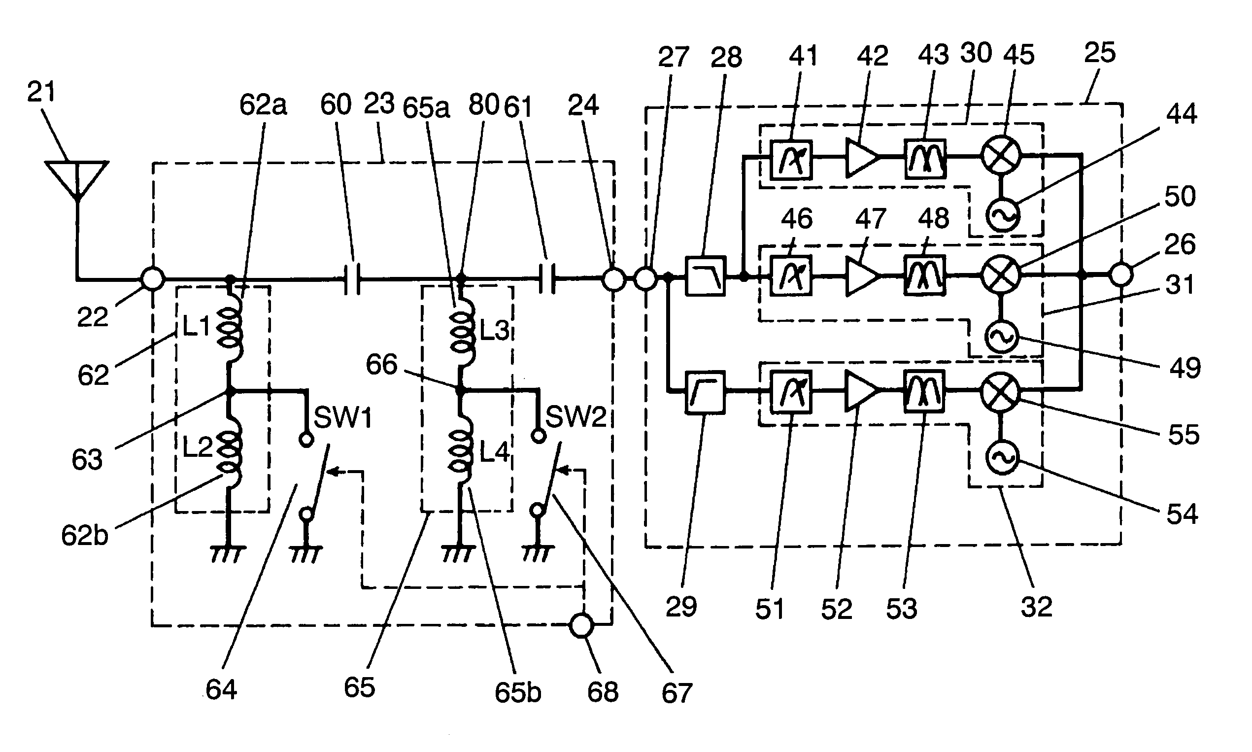
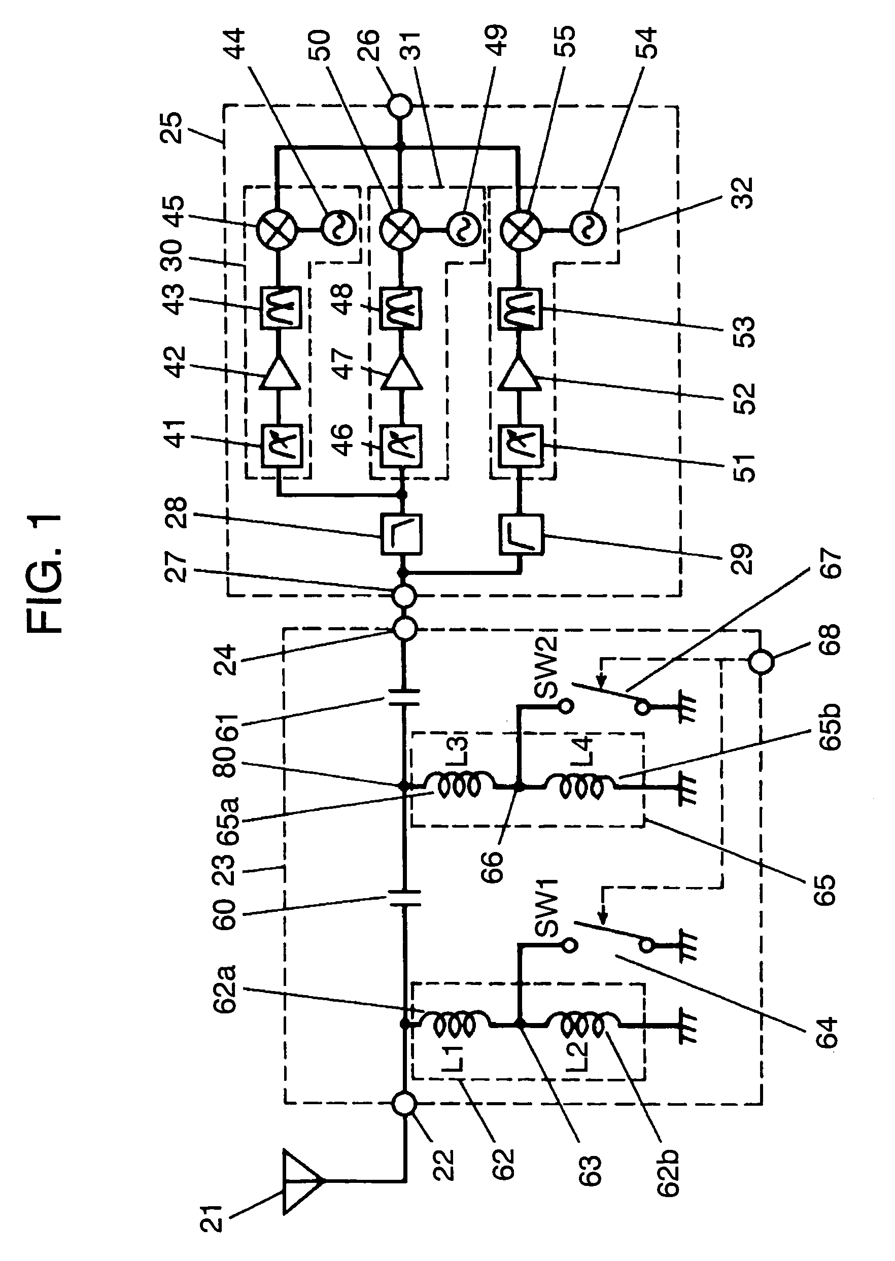
[0025]The first embodiment is demonstrated hereinafter with reference to accompanying drawings. FIG. 1 is a block diagram of a matching unit in accordance with the first exemplary embodiment of the present invention. Rod antenna 21 receives television broadcasting waves ranging from ca. 50 MHz to 900 MHz and has a length of ca. 40 mm. Since antenna 21 is made of brass, resistance of antenna is small and loss in high-frequency signal is also small, so that an antenna having excellent receiving-sensitivity is obtainable.

[0026]Matching unit 23 includes input terminal 22 that is connected to antenna 21, and output terminal 24 that is connected to electronic tuner 25. Tuner 25 selects a desirable channel and converts the signal into the intermediate frequency (IF) signal (58.75 MHz in Japan, and 45.75 MHz in the USA) before outputting the IF signal from output terminal 26 of the tuner.

[0027]Next, electronic tuner 25 is detailed. Tuner 25 receives signals of both the VHF and the UHF bands...

exemplary embodiment 2

[0063]The second exemplary embodiment is demonstrated hereinafter with reference to accompanying drawings. FIG. 9 shows a circuit diagram of a matching unit in accordance with the second embodiment, and FIG. 10 shows a component layout of the matching unit. In those drawings, similar elements to those in FIG. 12 and FIG. 1 have the same reference marks, and the descriptions thereof are omitted. In FIG. 9, first inductor 62 is formed of a series connecting unit comprising inductors 130, 131 and 132, which are connected in series in this order from the input terminal 22. Second inductor 65 is formed of a series connecting unit comprising inductors 133, 134 and 135.

[0064]Switches 64 and 67 are formed of a circuit comprising three diodes. A series connecting unit formed of capacitors 136 and 137 is interposed between junction points 63 and 66, and diode 138 is interposed between those capacitors. The cathode of diode 138 is coupled with the anode of diode 139, and the cathode of diode 1...

exemplary embodiment 3

[0074]The third exemplary embodiment is demonstrated hereinafter with reference to FIG. 11, which shows a sectional view of a high-frequency receiver in accordance with the third exemplary embodiment and employing the matching unit used in the second embodiment. In FIG. 11, fixing section 21a prepared at the end of antenna 21 is rigidly mounted to housing 160 of the high-frequency receiver. Tip 21b of antenna 21 is connected to printed circuit board 161 disposed in housing 160 with solder 162. Antenna 21 includes movable section 163 between its main body 21c and fixing section 21a. Movable section 163 is supported by a shaft such that it can rotate around two axes, namely, in both directions A and B. Board 161 has matching unit 23, and its input terminal is electrically connected to antenna 21 with solder 162.

[0075]The high-frequency receiver discussed above is capable to obtain an optimum sensitivity by moving antenna 21 around movable section 163, thereby compensating antenna 21 f...


PUM


Abstract

A matching unit includes a switching means for switching an inductance of a first inductor. This switching means sets an inductance such that a first inductor shows an inductance property to both of the VHF low-band and high-band, and shows a capacitance property to the UHF band. This structure allows the matching unit to achieve the matching for both the VHF low-band and high-band by just switching the two circuits of the VHF low-band and high-band, also allows the matching unit to show a capacitance property to the UHF band. Thus the loss produced in transmitting signals can be reduced, and the circuit can be simplified. As a result, the matching unit can be downsized, and the cost can be reduced.

Description

FIELD OF THE INVENTION[0001]The present invention relates to matching units to be used for receiving television broadcasts.BACKGROUND OF THE INVENTION[0002]A conventional matching unit is described hereinafter with reference to FIG. 12, which shows a block diagram of the conventional matching unit. High frequency signals ranging between from ca. 500 MHz to 900 MHz input to Antenna 1 for receiving signals of both the VHF and the UHF bands. An output from antenna 1 is fed into matching unit 12 having input terminal 2 and output terminal 3, and an output signal supplied from output terminal 3 is fed into electronic tuner 4. Tuner 4 selects the signal of a desirable channel and converts the signal into the given intermediate frequency (IF) signal, then outputs the signal from output terminal 5.[0003]Between input terminal 2 and output terminal 3 of matching unit 12, a first series connecting unit formed of first switch 6 and low pass filter (LPF) 7 is interposed. A second series connect...

Claims


Application Information

Patent Timeline
Patent Type & Authority Patents(United States)
IPC IPC(8): H04B1/18H03H7/38H03F1/56H03H7/075H03H11/40H04N5/44H04N5/50
CPCH03F1/565H04B1/18H03H11/40H04B1/005H04B1/006H03H7/38H03F2200/111H03F2200/252H04N5/50
Inventor HIBINO, YASUHIROKAMIMOTO, RYUICHIITO, AKIRA
Owner PANASONIC CORP
Why Eureka
Try Eureka