Driver circuit and method for driving an electronic component

a technology of electronic components and drive circuits, applied in the direction of lasers, electric pulse generators, electric variable regulation, etc., can solve the problems of undesirable transient oscillations or so-called ringing processes, undesirable consequences, and undesirable transient oscillations or ringing processes, so as to reduce the quality of resonant, improve the total required chip surface area, and be easily integrated into a monolithic integrated circuit

Inactive Publication Date: 2006-12-05
ATMEL GERMANY
View PDF20 Cites 16 Cited by
  • Summary
  • Abstract
  • Description
  • Claims
  • Application Information

AI Technical Summary

Benefits of technology

[0008]It has been achieved and demonstrated according to the invention, that the frequency-dependent realization of the mirror factor of a current mirror, in sum, leads to reduced transient oscillations or ringing processes when switching between current levels. According to the invention with the frequency-dependent mirror factor, it is possible to drive and activate electronic components, and especially laser diodes for example, with current pulses of high amplitude up to a few hundred mA, with short rise times and fall-off times in the range of less than one nanosecond, with reduced initial transient oscillations or ringing processes when switching between the discrete current levels.
[0017]Still further it is preferred that an n-well of a pnp-transistor or a p-well of an npn-transistor is connected via a damping resistor to a reference potential. Thereby, it is achieved that the displacement current flowing through the capacitance of the associated pn-junction can flow away directly to the supply voltage. As a result, the n- or p-layer, which is often embodied as a well, is held to a constant potential. In this manner, undesired displacement currents, which can arise due to the relatively large capacitance between the well and the substrate, are suppressed or held to a small value. In that context, the resistor achieves a reduction of the quality of the resonant or oscillating circuit that arises in connection with the inductance of the conductor lines leading to the electronic component, for example, the laser diode. Finally, this measure or feature also leads to a reduction of the initial transient oscillations or ringing processes.

Problems solved by technology

In the generation of such current pulses, there is the general problem that transient oscillations or so-called ringing processes arise when controlledly switching the driver voltage and / or the driver current from a first level to a second level.
These transient oscillations or ringing processes are undesirable and have undesirable consequences.
This approach is problematic, however, because it sharply reduces the rise rate and / or the fall-off rate of the current.
A further disadvantage is that the unavoidable housing and bond capacitances nonetheless remain effective and thus reduce the efficacy of the suggested measures for reducing the oscillating circuit quality.
Moreover, actually carrying out the proposed measures requires a considerable chip surface area when fabricating the driver circuit as an integrated circuit.

Method used


Image

  • Driver circuit and method for driving an electronic component
  • Driver circuit and method for driving an electronic component
  • Driver circuit and method for driving an electronic component

Examples


Embodiment Construction

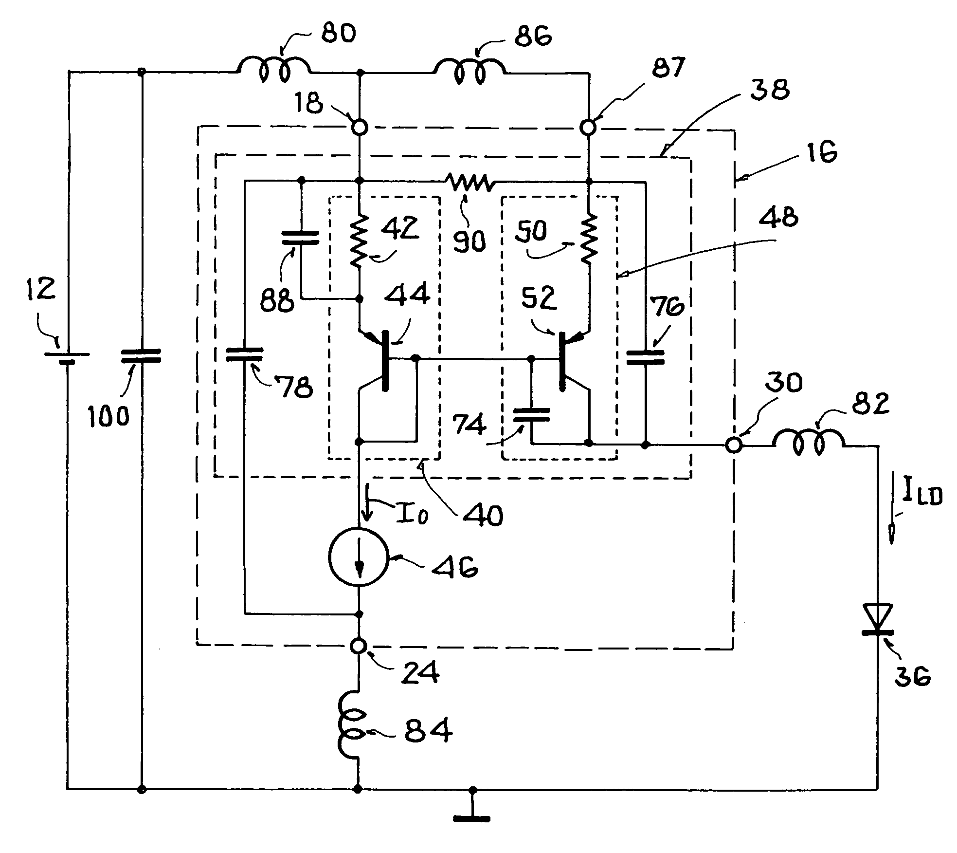
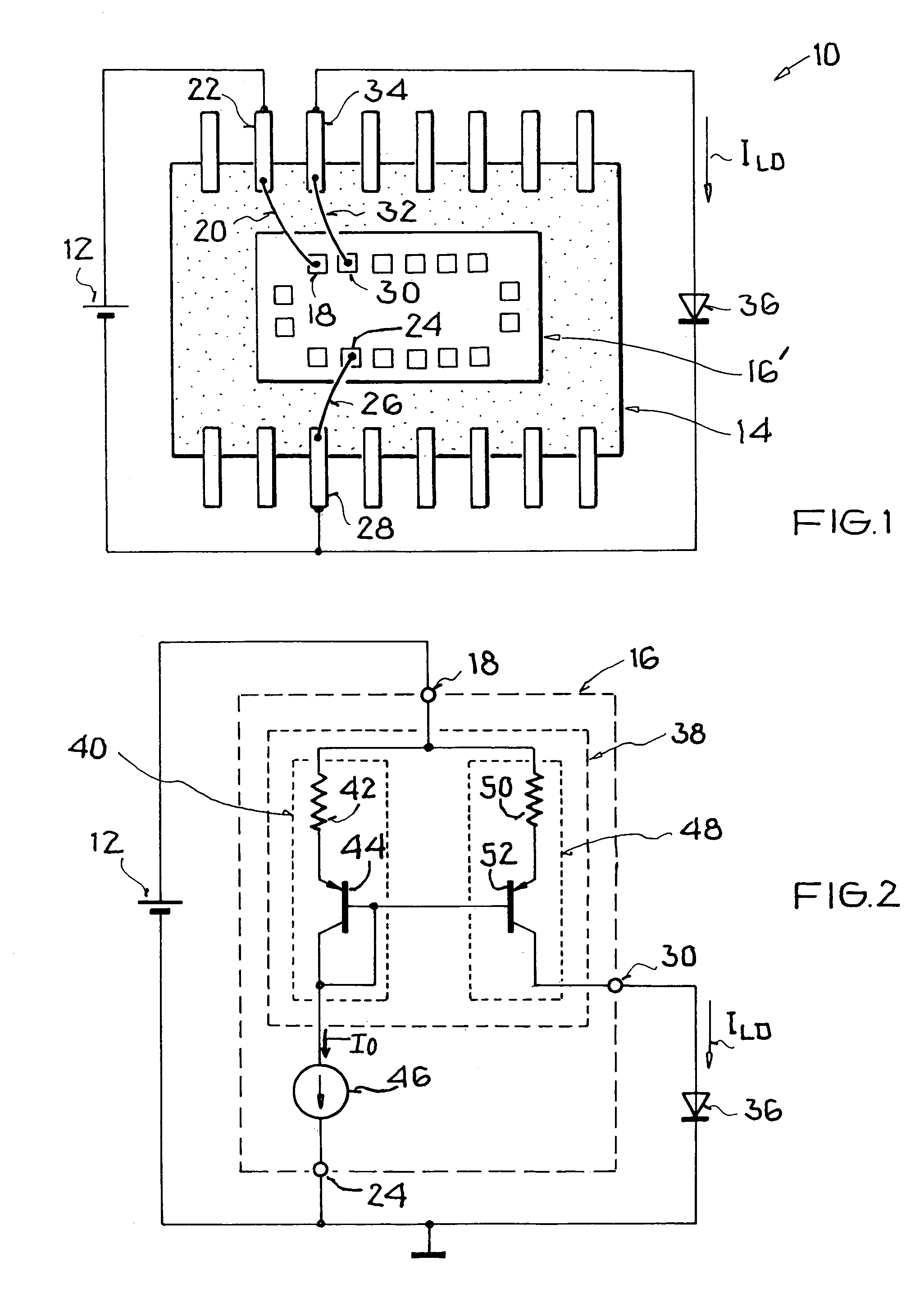
[0028]FIG. 1 generally and schematically shows a circuit 10 representing an application of a driver circuit for a laser diode 36. The circuit 10 comprises a supply voltage source 12, which supplies electrical power (voltage and / or current) to a driver component 14 including a driver chip 16′. The driver chip 16′ comprises at least a first supply voltage input connection or terminal 18, which is connected via a bond wire 20 with a connection pin 22 on the driver component 14. Furthermore, the driver chip 16′ comprises at least one ground connection or terminal 24, which is connected via a bond wire 26 with a ground connection pin 28 on the driver component 14. The two connection pins 22 and 28 are connected with various outputs of the supply voltage source 12, so that an appropriate supply voltage is applied to the driver chip 16′ via its supply voltage input terminal 18 and its ground terminal 24. Namely, this supply voltage is provided by the supply voltage source 12 to the driver ...


PUM


Abstract

A driver circuit and a method drive an electronic component such as a laser diode with a variable electric current that is controlledly switched between at least two discrete current levels. The driver circuit includes circuit elements that damp ringing or initial transient oscillations that arise when switching the current between the current levels. The driver circuit includes a current mirror having a mirror amplification factor dependent on the frequency of the variable electric current. In order to counteract parasitic capacitances and / or inductances leading to the ringing, an inductance and / or a resistance are connected between the two series circuits making up the current mirror, a capacitance is connected parallel to a reference resistor of one of the series circuits, and / or a capacitance is connected across the voltage supply.

Description

PRIORITY CLAIM[0001]This application is based on and claims the priority under 35 U.S.C. §119 of German Patent Application 103 23 669.4, filed on May 14, 2003, the entire disclosure of which is incorporated herein by reference.FIELD OF THE INVENTION[0002]The invention relates to a driver circuit and a method of driving it, for driving an electronic component with a variable electric current that is controlled to switch between at least two discrete current levels.BACKGROUND INFORMATION[0003]Laser diodes represent an example of an electronic component that can be driven with such a driver circuit of the above-mentioned general type. A driver circuit of this type for driving laser diodes is known from the European Patent Publication EP 0,810,700 A2.[0004]Semiconductor lasers based on laser diodes are used, for example, for recording or writing data into storage media such as CDs and DVDs. Such writing of data takes place at a high speed and thus requires the laser device to provide op...

Claims


Application Information

Patent Timeline
Patent Type & Authority Patents(United States)
IPC IPC(8): H01S3/00G05F3/26H01S5/022H01S5/042H03K17/16H03K17/60H05B44/00
CPCG05F3/265H01S5/0428H01S5/042
Inventor BERGMANN, GUENTHERDOTZAUER, ERWINVOGELMANN, HOLGERKNOTZ, HERBERTWERNIG, WOLFGANG
Owner ATMEL GERMANY
Why Eureka
Try Eureka