Low temperature sputter target/backing plate method and assembly

a low-temperature, backing plate technology, applied in vacuum evaporation coating, non-electric welding apparatus, manufacturing tools, etc., can solve the problems of high sputtering rate, high sputtering rate bowing or bending, leakage, etc., to achieve high sputtering rate without significant bowing or bending, and ensure the effect of separation

Inactive Publication Date: 2006-12-12
TOSOH SMD
View PDF9 Cites 67 Cited by
  • Summary
  • Abstract
  • Description
  • Claims
  • Application Information

AI Technical Summary

Benefits of technology

[0013]Although the preferred target material and backing plate material have dissimilar thermal expansion coefficients, the bonding methods of the present invention allow these unconventional assemblies to be bonded together and used at high sputtering rates without significant bowing or bending and without separation adjacent the periphery. Additionally, the low temperature pressure consolidation methods of the present invention do not cause undesirable grain growth of the target material during bonding of the target material with the backing plate material. The bonding methods of the present invention have been found to be particularly useful with regard to joining titanium (Ti) materials with aluminum (Al) materials; welding of such materials to one another imparts formation of brittle intermetallic compounds.
[0014]A second objective of the present invention provides for simplification of joining the target material and backing plate material free of conventional welding or high temperature bonding techniques. In most cases, the circumferentially extending mechanical bond in accordance with the present invention along the periphery zone provides sufficient resistance to separation. In cases where increased bond strength is desired, a series of interlocking protruding portions are formed in the target material or backing plate material mating surface and become imbedded in the mating material subsequent to being low temperature pressure consolidated. In an alternate embodiment, grooves can be formed in the opposing mating surface, designed to receive the protruding portions and provide additional mechanical interlocking, with additional bonding strength, between the target and backing plate material.

Problems solved by technology

Magnetron sputtering imposes considerable thermal energy upon the sputter target assembly, especially within the concentrated annular region of the target raceway.
These bonding methods typically involve imposition of high temperatures.
Sputter target assemblies bonded by these methods can bow or bend at high sputtering rates, especially when a large difference exists between the coefficients of thermal expansion for the target material and backing plate material.
In sputter target assemblies with internal cooling channels, bowing and bending induces leakage; the typical bonding methods, described above, tend to deform, or otherwise partially constrict, the cooling channels.
Additionally, known bonding techniques, as discussed above, result in undesirable grain growth in the target material or the resulting bond cannot withstand the stresses imposed by high sputtering rates.
The method results in a strong bond with increased shear resistance such that the target assembly can withstand thermal stress that otherwise may tend to result in debonding or target assembly warpage during use.
For the reasons mentioned above, conventional welding techniques, even along only the periphery zone, are undesirable.

Method used


Image

  • Low temperature sputter target/backing plate method and assembly
  • Low temperature sputter target/backing plate method and assembly
  • Low temperature sputter target/backing plate method and assembly

Examples


Embodiment Construction

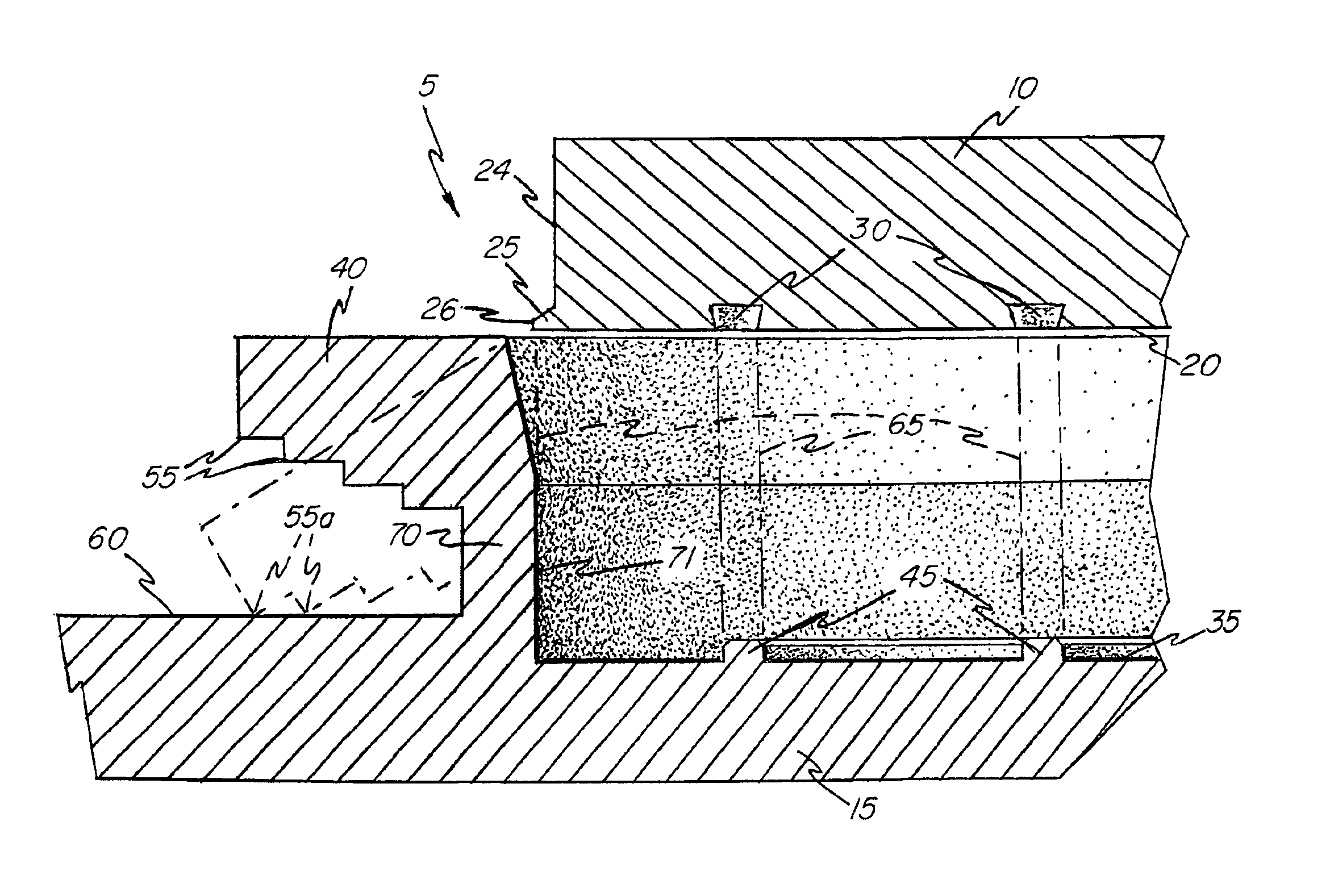
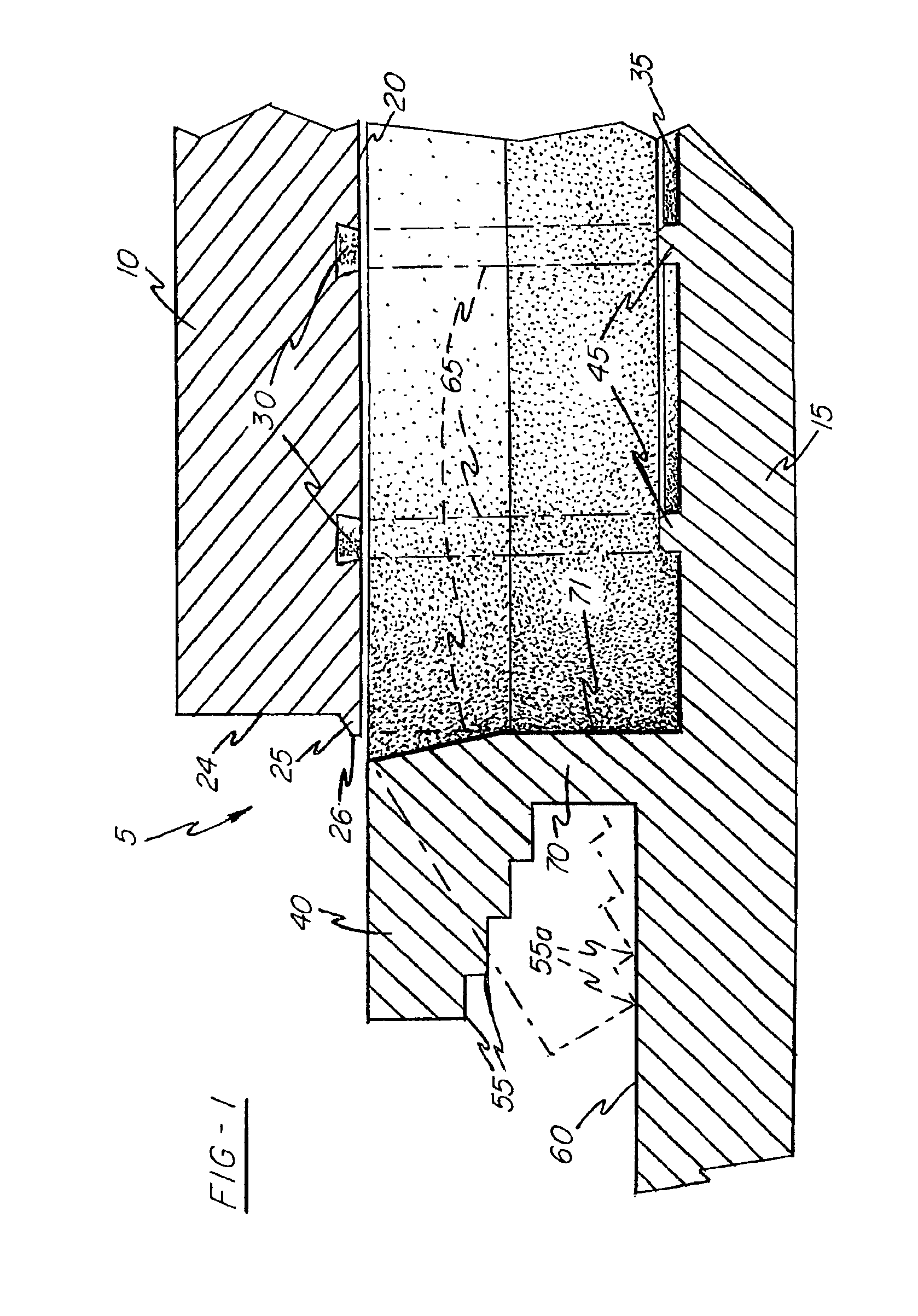
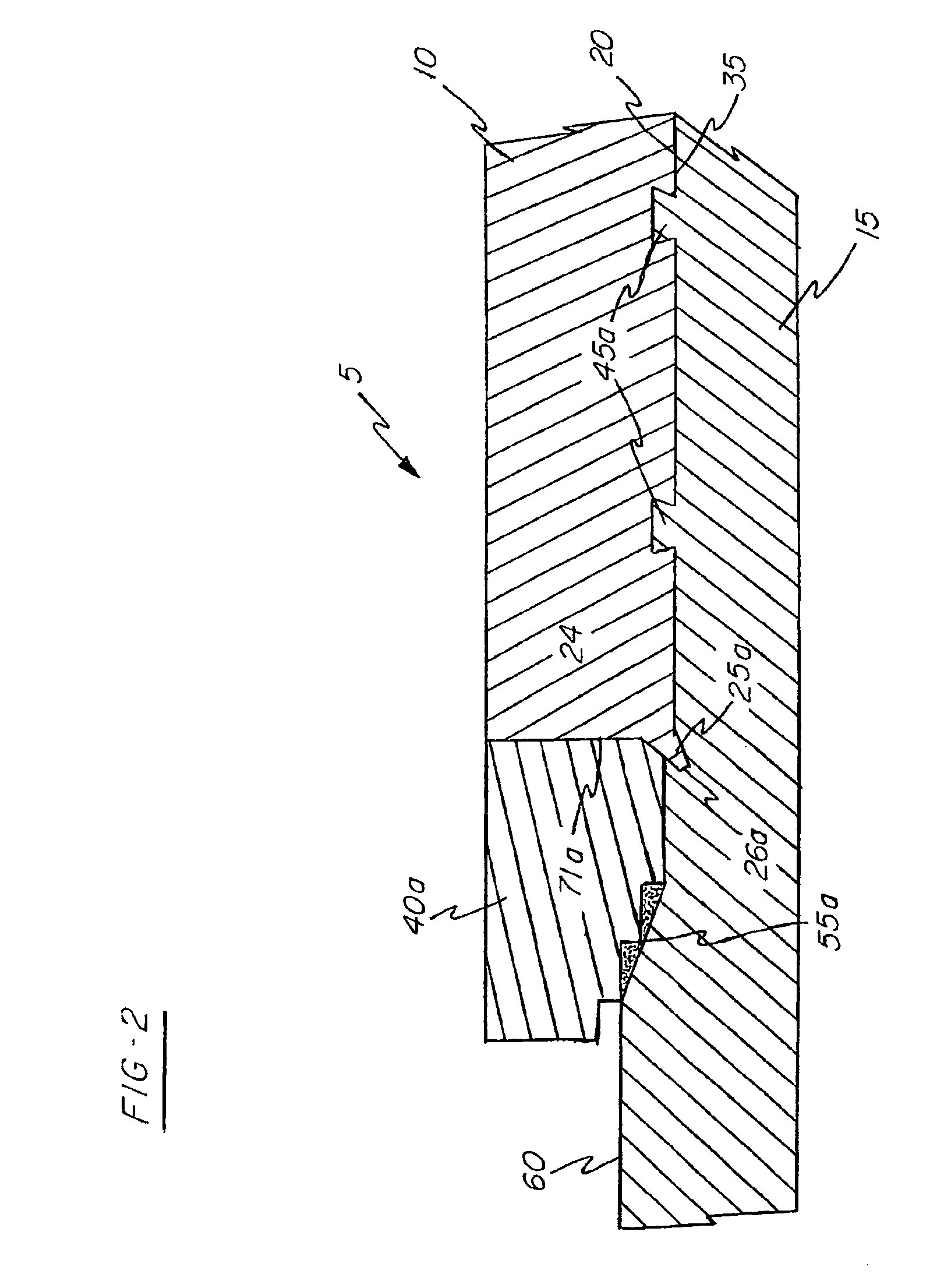
[0025]Referring initially to FIG. 1, target assembly 5 in accordance with the present invention is depicted prior to the target material 10 being low temperature pressure consolidated with backing plate material 15. As shown, the target material is first formed to be substantially disc shape and the backing plate material is formed to receive the target material within. Exemplary target materials comprise, Al, Cu, Ti, Co, and their alloys. Exemplary backing plates may comprise Al, stainless steel, Cu, Ti, and their alloys.

[0026]The target material 10 is formed to include a mating surface 20 with tapered grooves 30 and a side portion 24. The target material is further formed to include a lip 25 extending from the side portion 24. The lip 25 is substantially rectangular in cross section with tip 26 defining the outer most edge of the target material in a radial direction.

[0027]The backing plate material 15 is formed to include a mating surface 35 with protruding portions 45 extending ...


PUM

PropertyMeasurementUnit
temperatureaaaaaaaaaa

Abstract

A sputtering target and a backing plate are diffusion-bonded with or without an insert or inserts interposed there-between so as to have a solid phase diffusion-bonded interface. The sputtering target substantially maintains its metallurgical characteristic and properties even though it has been diffusion-bonded to the backing plate. The solid-diffusion bonding of the target and backing plate, is achieved at a low temperature and pressure and results in interdiffusion of constituent atoms to attain high adhesion and bond strength without attendant deterioration or large deformation of the target material, while inhibiting the crystal growth in the target material. The bond undergoes no abrupt decrease in bond strength upon elevation of the service temperature. One hundred percent bonding is achieved with non-bonded portions such as pores left along the interface.

Description

CROSS-REFERENCE TO RELATED APPLICATION[0001]Priority filing benefit of (1) International PCT application PCT / USO1 / 49126 filed Dec. 17, 2001, and published under PCT 21(2) in the English language and (2) U.S. provisional application Ser. No. 60 / 255,873 filed Dec. 18, 2000 is hereby claimed.FIELD OF THE INVENTION[0002]The present invention relates to sputter target assemblies for use within sputtering systems. More specifically, the present invention pertains to sputter target assemblies which include a target material bonded by low temperature pressure consolidation to a backing plate material with a mechanical bond around the periphery thereof.BACKGROUND OF THE INVENTION[0003]Cathodic sputtering is widely used for the deposition of a thin film, or layer, of material onto desired substrates. The sputtering process employs gas ion bombardment of a target material having a face formed of a material that is to be deposited as a thin film, or layer, on the given substrate. Ion bombardmen...

Claims


Application Information

Patent Timeline
Patent Type & Authority Patents(United States)
IPC IPC(8): B23P11/00C23C14/34H01J37/34
CPCC23C14/3407C23C14/3414H01J37/3435H01J37/3491Y10T29/49936Y10T29/49995Y10T29/49945B23K20/00
Inventor IVANOV, EUGENE Y.
Owner TOSOH SMD
Why Eureka
Try Eureka