
Channel estimation method for a mobile communication system

a mobile communication system and channel estimation technology, applied in the field of ideal channel estimation method for a communication apparatus, can solve the problems of significant deterioration of communication quality, so as to enhance the accuracy of channel estimation result calculation, improve characteristics, and eliminate thermal noise

Active Publication Date: 2007-01-02
MAXELL HLDG LTD
View PDF9 Cites 18 Cited by
  • Summary
  • Abstract
  • Description
  • Claims
  • Application Information

AI Technical Summary

Benefits of technology

[0017]To achieve the aforementioned object, the present invention improves characteristics by calculating the channel estimation results variously for all data signal symbols and using them for demodulation. To accomplish the object, the present invention also pays attention to the frequency characteristics of fading in a radio propagation path and enhances the accuracy in channel estimation result calculation by eliminating the thermal noise that would increase the estimation error.

Problems solved by technology

If the channel is affected by fading, noise, or the like at the time of P3 when the channel estimation method shown in FIG. 6 is used, the communication quality may deteriorate due to improper channel estimation.
If the pilot signals are affected by fading, noise, or the like during the use of the channel estimation method shown in FIG. 8, the communication quality may deteriorate due to improper channel estimation.
Therefore, if the same channel estimation result is used for a plurality of data signals (symbols), the communication quality significantly deteriorates due to incorrect channel variation estimation.
Further, even if a conventional method is used to achieve channel estimation by weighting pilot signals prevailing at a plurality of times, there are no quantitative calculation grounds for weighting coefficients.
Therefore, if the coefficients are improperly set, the communication quality may seriously deteriorate.

Method used


Image

  • Channel estimation method for a mobile communication system
  • Channel estimation method for a mobile communication system
  • Channel estimation method for a mobile communication system

Examples


first embodiment

[0036]To achieve the object described above, the present invention uses a pilot signal sampling frequency that is equivalent to the data signal transmission rate (symbol rate), and uses a single pilot signal or a plurality of weighted pilot signals to achieve channel estimation for each data signal symbol. More specifically, the present invention estimates the data signal's amplitude variation or phase rotation during propagation.

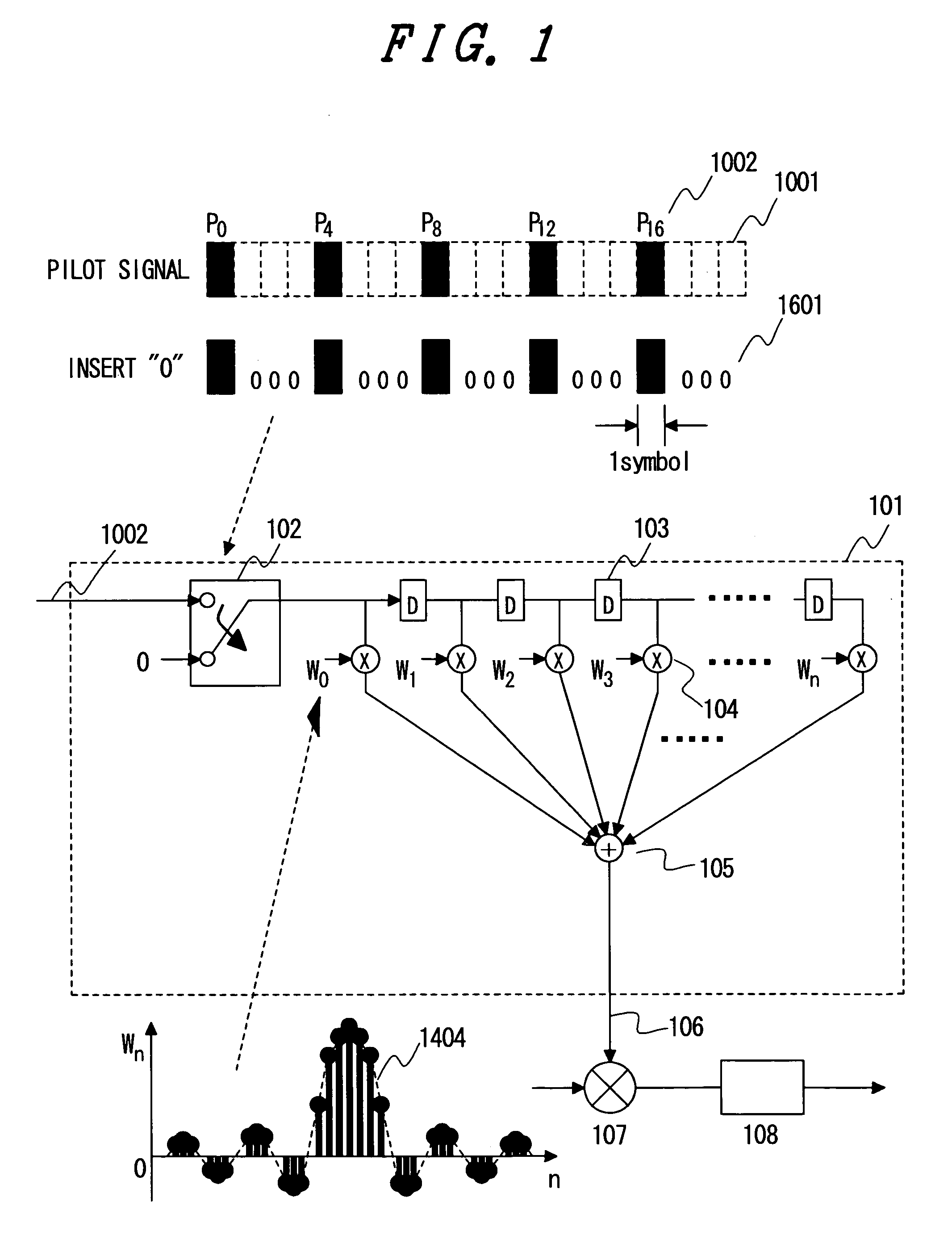
[0037]Pilot signals (P0, P1, P2, P3, P4, . . . ) 1001 are transmitted or sampled at the same transmission rate (symbol rate) as for data signals 1005. In FIG. 10, the pilot signals P0, P4, P8, P12, and P16 (1002), which picked up at 4-symbol intervals, are multiplied by weighting coefficients (1003) and added together (1004) to calculate the channel estimation result for a certain symbol d1 (1006) within the data signals 1005. An alternative is to use only pilot signal P8, which is received at the same or closest time, for calculating the channel estimation...

second embodiment

[0039]In a second embodiment, a received pilot signal is used as an input and allowed to pass through a low-pass filter (LPF) for the purpose of enhancing the channel estimation accuracy. The second embodiment will now be described in detail.

[0040]In a radio propagation path, fading occurs in which the amplitude and phase drastically change (a sort of noise). When this phenomenon is expressed in terms of a frequency region, no frequency components exceed the maximum Doppler frequency (=fd). The maximum Doppler frequency is proportional to the carrier wave frequency and mobile station's moving speed. If, for instance, the carrier wave frequency is 2 GHz and the mobile station's movement speed is 120 km / h, the maximum Doppler frequency (fd) is substantially equal to 240 Hz (equivalent to 240 bps) so that the substantial spectral density is as indicated by 1101 in FIG. 11.

[0041]Meanwhile, the data transmission rate of, for instance, the third-generation cellular phone is 384 kbps. The ...

third embodiment

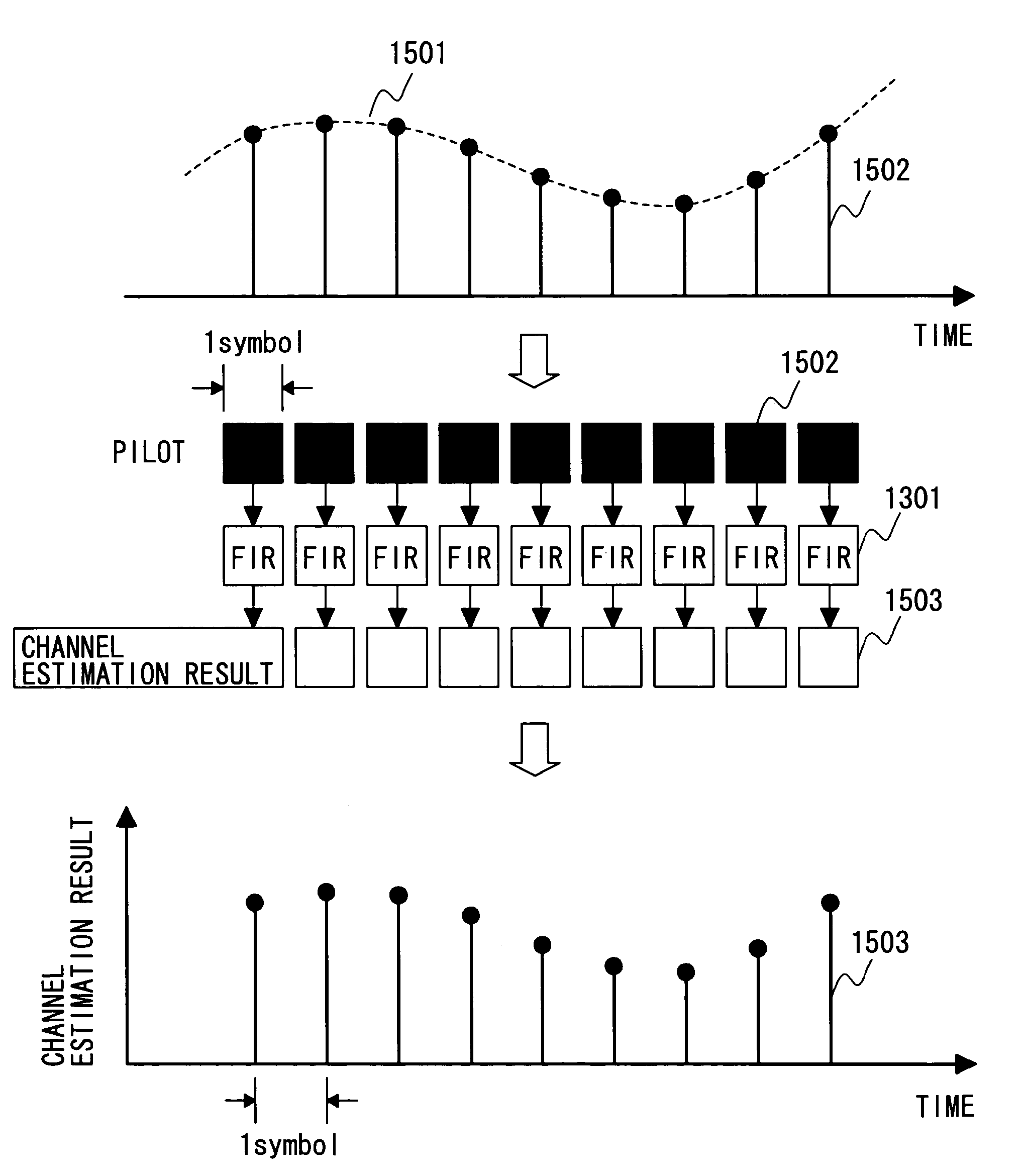
[0043]The description of a third embodiment relates to the configuration of a low-pass filter that is used in the second embodiment. For calculating the channel estimation result, which varies from one data signal symbol to another as mentioned in the description of the first embodiment, the pilot signal transmission or sampling intervals are the same as those for the data signal. In the first embodiment, pilot signals at a plurality of times are weighted and added together. However, the simplest method for achieving this object is the use of an FIR filter 1301 shown in FIG. 13. The FIR filter comprises a plurality of delay devices 1303, multipliers 1304 for multiplying weighting coefficients for respective data, and an adder 1305 for adding up the obtained multiplication results. As shown in FIG. 14, various FIR filter coefficients are set as weighting coefficients in accordance with an impulse response 1402, which is determined by a Fourier transform of desired low-pass characteri...


PUM


Abstract

Under present circumstances, where an increasing number of wireless communication systems employ the QAM method as a modulation method for frequency use efficiency enhancement as the speed of information transmission in the wireless communication systems increases, it is an object of the present invention to provide a channel estimation method for estimating a channel efficiently and accurately and establishing communication at high quality, that is, providing communication with excellent error rate characteristics. To achieve the above object, the present invention improves characteristics by calculating the channel estimation results variously for all data signal symbols and using them for demodulation. To accomplish the object, the present invention also pays attention to the frequency characteristics of fading in a radio propagation path and enhances the accuracy in channel estimation result calculation by using a band pass filter for eliminating the thermal noise that would increase the estimation error.

Description

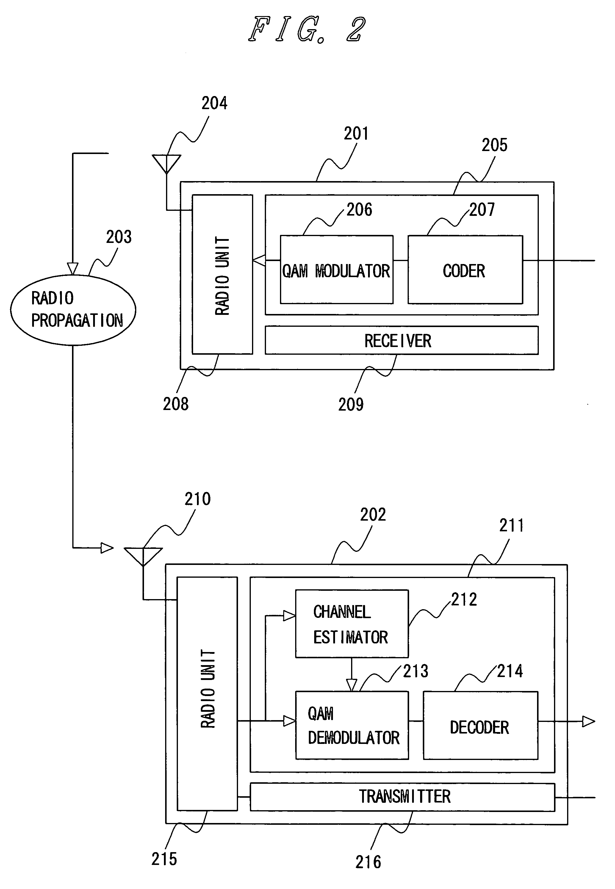
FIELD OF THE INVENTION[0001]The present invention particularly relates to an ideal channel estimation method for a communication apparatus at a receiving end, which is used with a wireless communication system.BACKGROUND OF THE INVENTION[0002]FIG. 2 illustrates the configurations of wireless communication apparatuses and wireless communication system to which the present invention applies. A wireless communication system comprises a wireless communication apparatus at a transmitting end 201 and a wireless communication apparatus at a receiving end 202 and provides phone calls and data transmissions via a radio propagation path 203. Although FIG. 2 and subsequent figures depict only one of two links, such as a downlink, the present invention is equally applicable to both an uplink and downlink.[0003]In the communication apparatus at a transmitting end 201, the data to be transmitted is first encoded by a encoder 207 in a transmitter 205. For wireless communication, convolutional codi...

Claims


Application Information

Patent Timeline
IPC IPC(8): H04B17/00H04B7/216H04Q7/28H04L27/38H04B3/06H04B7/005H04L25/02H04L27/01
CPCH04L25/0232
Inventor HANAOKA, SEISHIYANO, TAKASHI
Owner MAXELL HLDG LTD
Learn More