Far infrared tandem low energy optical power limiter device

a low energy, optical power limiter technology, applied in the direction of optics, non-linear optics, optical radiation measurement, etc., can solve the problems of low transmission and unsatisfactory low damage threshold, and achieve the effect of reducing the damage threshold, and improving the damage threshold of the devi

Inactive Publication Date: 2007-02-13
UNITED STATES OF AMERICA THE AS REPRESENTED BY THE SEC OF THE ARMY
View PDF8 Cites 13 Cited by
  • Summary
  • Abstract
  • Description
  • Claims
  • Application Information

AI Technical Summary

Benefits of technology

[0010]The second embodiment is a slight variation of the first embodiment and is comprised of adding a second layer of VO2 to the first embodiment between the input antireflective coating layer and the input window layer. Operationally, the second layer of VO2 limiter will heat up very quickly with higher input energy and will switch on to reflect the subsequent higher input energy before the input energy even gets to the input window. The purpose of this embodiment is to limit the energy to the remainder of the downstream optical power limiters when a higher input radiation than what is required for the switching of the chalcogenide layer limiter enters the device. Another advantage of the second embodiment over the first is that at a high threat radiation level, the radiation is reflected rather than absorbed thereby protecting the device.
[0012]The damage threshold of the device is improved by the window material being made of zinc selenide or germanium since these materials have higher damage thresholds than the VO2. The damage threshold of the device may be further improved by putting a diamond-like carbon coating layer on the window layers. The germanium optical power limiter between the chalcogenide and VO2 layers has the added advantage that it may facilitate their bonding.

Problems solved by technology

The VO2 device has a low switching threshold, but also has the undesirable low damage threshold and low transmission.

Method used


Image

  • Far infrared tandem low energy optical power limiter device
  • Far infrared tandem low energy optical power limiter device
  • Far infrared tandem low energy optical power limiter device

Examples


Embodiment Construction

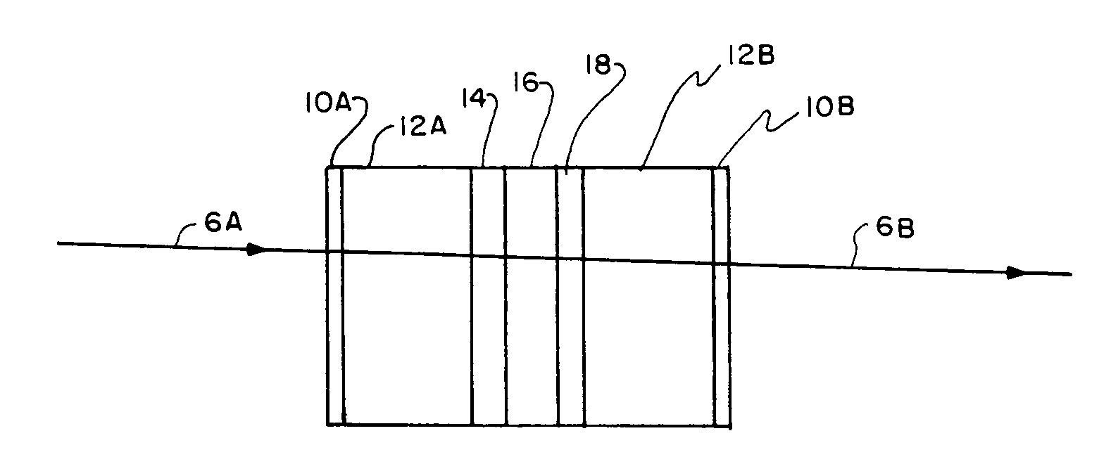
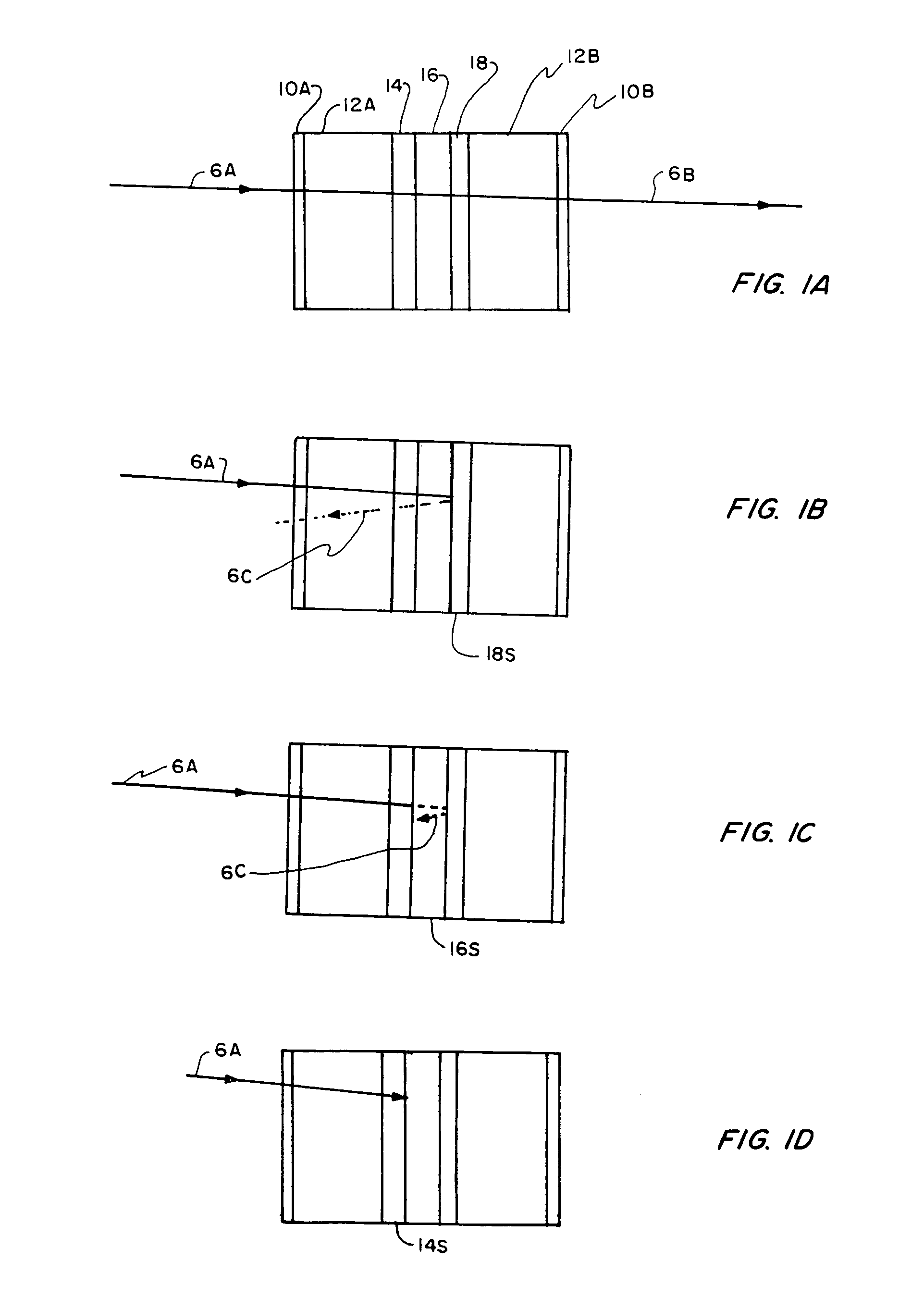
[0015]Refer to FIGS. 1A through 1D for an explanation of one embodiment of the device. FIG. 1A illustrates the device in the unswitched highly transmissive state where the output radiation energy 6B is generally more than 80% of the input radiation energy 6A as long as 6A is below a threshold level. That is, as long as 6A is below the threshold level, the plurality of tandem optical power limiter layers 14, 16, and 18 will not increase in temperature to the self-activated state, i.e. switch on from the transmissive to either the reflective or absorptive states. An input antireflective coating layer 10A and input window substrate layer 12A are on the input side of the chalcogenide layer 14, the germanium layer 16, and the VO2 layer 18. At the output of layer 18 are the output window substrate layer 12B and output antireflective coating layer 10B.

[0016]FIG. 1B illustrates schematically what happens when the input radiation energy, perhaps from an adversary intending to damage the ther...


PUM

PropertyMeasurementUnit
temperatureaaaaaaaaaa

Abstract

Two embodiments of a multilayered low energy optical power limiter device are disclosed which protect thermal sensors against laser threats in the far infrared spectral region. One limiter device has multiple layers in order from the incoming radiation side an antireflective coating layer, a window substrate layer, a layer of chalcogenide, a germanium substrate layer, a layer of vanadium dioxide (VO2), a window substrate, and an antireflective coating layer. As incoming radiation energy increases, the VO2 layer will heat up and change from an unswitched transmissive state to a switched reflective state. The excessive energy past the switched state is reflected back through the germanium and chalcogenide layer and is absorbed quickly therein so that these layers also heat up quickly and are switched almost simultaneously with the VO2 layer to provide high optical density at a low switching threshold temperature with high damage threshold. The second embodiment further adds a second VO2 layer between the input antireflective coating layer and window substrate layers to reflect high radiation energy immediately.

Description

[0001]The invention described herein may be manufactured, used, and licensed by the U.S. Government for governmental purposes without the payment of any royalties thereon.BACKGROUND OF INVENTION[0002]1. Field[0003]The present invention relates to an optical power limiter device for protecting thermal sensors against threat incoming radiation, and especially to providing a plurality of optical power limiters in tandem between window substrates with each limiter having a progressively lower switching threshold temperature to the incoming radiation so that the last limiter is usually the first to switch on by increasing temperature and reflect back the radiation for a second pass through the other limiters and quickly raise their temperatures to threshold level in which the tandem of limiters essentially switch on sequentially to provide increase in optical density for the device.[0004]2. Prior Art[0005]It is highly desirable to protect sensitive thermal sensors against threat laser ra...

Claims


Application Information

Patent Timeline
Patent Type & Authority Patents(United States)
IPC IPC(8): G02F1/01
CPCG01J1/04G01J1/0418H01S3/005G02F1/0147G01J2001/0285G02F2201/38G02F2201/50G02F2203/52
Inventor AHN, BYONG H.
Owner UNITED STATES OF AMERICA THE AS REPRESENTED BY THE SEC OF THE ARMY
Why Eureka
Try Eureka