Light emitting element

a technology of light-emitting elements and elements, applied in the field of light-emitting elements, can solve problems such as failure to provide sufficient enduran

Inactive Publication Date: 2007-03-13
UDC IRELAND +1
View PDF15 Cites 48 Cited by
  • Summary
  • Abstract
  • Description
  • Claims
  • Application Information

AI Technical Summary

Benefits of technology

[0016]With regard to the above-mentioned specific compound, the expression, “consisting essentially of carbon, fluorine and nitrogen” refers to the fact that most preferably, the compound contains no atoms other than carbon, fluorine and nitrogen atoms, that is, no atoms, including hydrogen atoms, other than these atoms. However, with respect to hydrogen atoms, the compound may contain not more than two hydrogen atoms (more preferably, not more than one) per six carbon atoms contained in the compound, and even in this case, the compound makes it possible to sufficiently provide the effects of the invention.
[0017]In the above-mentioned specific compound, the ratio of the number of fluorine atoms to the number of carbon atoms contained in a molecule is preferably from 55% to 90%, more preferably from 57% to 88%, and still more preferably from 60% to 85%.
[0018]When durability of the light emitting element is taken into consideration, a glass transition temperature (Tg) of the specific compound is preferably from 130° C. to 400° C., more preferably, from 135° C. to 400° C., still more preferably, from 140° C. to 400° C., particularly preferably, from 150° C. to 400° C., and most preferably, from 160° C. to 400° C.
[0019]In this case, the glass transition temperature (Tg) can be confirmed by thermal measurements, such as differential scanning calorimetry (DSC) and differential thermal analysis (DTA), X-ray diffraction (XRD), observation under a polarizing microscope or the like.
[0020]As will be described below, the light emitting element of the invention may utilize either light emission from an excited singlet state or light emission from an excited triplet state. However, when the light emitting element utilizes light emission from the excited triplet state, the above-mentioned specific compound preferably has a minimum excited triplet energy level (T1 level) from 65 kcal / mol (272.35 kJ / mol) to 95 kcal / mol (398.05 kJ / mol), more preferably, from 67 kcal / mol (280.73 kJ / mol) to 95 kcal / mol (398.05 kJ / mol), still more preferably, from 69 kcal / mol (289.11 kJ / mol) to 95 kcal / mol (398.05 kJ / mol), and particularly preferably, from 71 kcal / mol (297.49 kJ / mol) to 95 kcal / mol (398.05 kJ / mol).
[0021]The compound (specific compound) consisting essentially of carbon, fluorine and nitrogen used in the present invention will be described below.<Compound Represented by General Formula (A)>

Problems solved by technology

However, the conventional organic EL elements fail to provide sufficient endurance, and there is strong demand for development of organic EL elements having high luminance, high luminous efficiency, and superior endurance.

Method used


Image

  • Light emitting element
  • Light emitting element
  • Light emitting element

Examples


synthesis example 1

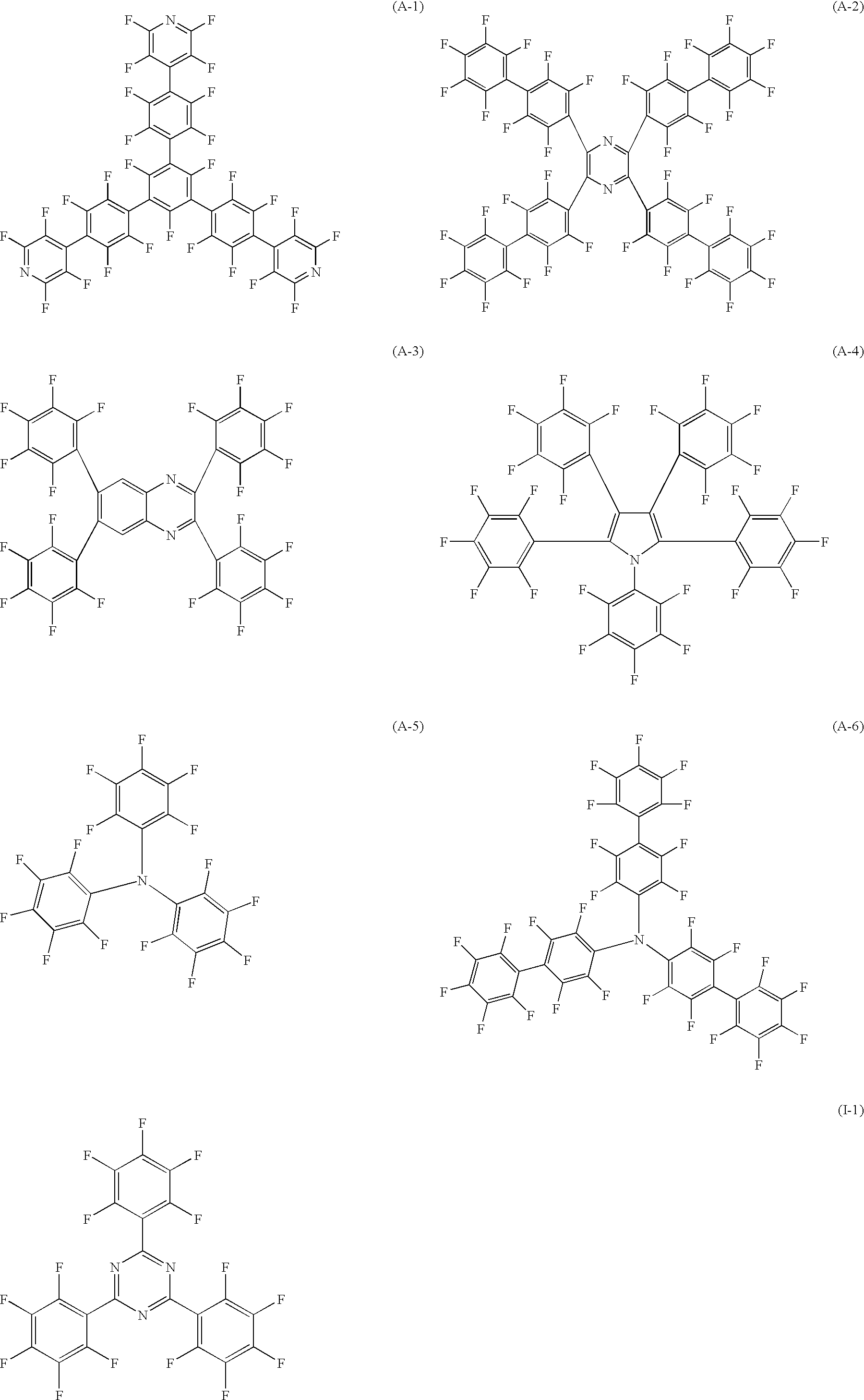
Synthesis of Exemplified Compound (I-1)

[0076]5.0 g of pentafluorobenzene (manufactured by Tokyo Kasei Kogyo Co., Ltd.) was dissolved in 120 mL of tetrahydrofran, and this solution was cooled to −70° C. 18.6 mL of n-butyl lithium / n-hexane solution (1.6 M)(manufactured by Wako Pure Chemical Industries, Ltd.) was slowly dripped thereto for 30 minutes. After completion of the dripping process, the resulting solution was stirred at −70° C. for 30 minutes. 50 mL of tetrahydrofran solution containing 1.83 g of cyanuric chloride (manufactured by Tokyo Kasei Kogyo Co., Ltd.) was dripped thereto at −70° C., and the resulting solution was heated to room temperature, and stirred for 1 hour at room temperature. The reaction product was put into water, and a deposited white solid matter was filtered out, and sufficiently washed with methanol and chloroform. After being dried, the structure of the example compound (I-1) was confirmed by using a mass-spectrum.

[0077]

example 1

Preparation of Organic EL Element

[0078]A glass substrate having dimensions of 25 mm×25 mm×0.7 mm, on which ITO was coated at a thickness of 150 nm (manufactured by Sanyo Vacuum Industries Co., Ltd.), was used as a transparent supporting substrate. After etching and washing the glass substrate, TPD (N,N′-diphenyl-N,N′-di(m-tolyl)-benzidine) was vapor-deposited thereon to a thickness of 50 nm, the following compounds a and b were vapor-deposited thereon at a mass ratio of 34:2 to a thickness of 36 nm, and the exemplified compound (I-1) was further vapor-deposited thereon at a thickness of 36 nm.

[0079]After providing a patterned mask (providing a light emission area of 4 mm×5 mm) on the organic thin film, lithium fluoride was vapor-deposited to a thickness of 3 nm, and then aluminum was vapor-deposited to a thickness of 60 nm, whereby an organic EL element of example 1 was produced.

Evaluation

Evaluation Method

[0080]The resulting organic EL element was subjected to light emission by appl...

example 2

[0089]α-NPD (N,N′-diphenyl-N,N′-di(α-naphthyl)-benzidine) was vapor-deposited to a thickness of 40 nm on an ITO substrate washed in the same manner as in example 1, a compound d shown below (blue light emitting material) was vapor-deposited to a thickness of 20 nm, and the exemplified compound (I-1) was vapor-deposited thereon to a thickness of 40 nm.

[0090]After providing a patterned mask (providing a light emission area of 4 mm×5 mm) on the obtained organic thin film, magnesium and silver (10 / 1) were simultaneously vapor-deposited to a thickness of 50 nm, and then silver was vapor-deposited to a thickness of 50 nm, whereby an organic EL element of example 2 was produced.

[0091]

[0092]The resulting organic EL element was evaluated in the same manner as in example 1. As a result, light emission with CIE chromaticity coordinates of (x, y)=(0.15, 0.28) was obtained, and the external quantum efficiency thereof was 3.0% (light emission from an excitation singlet state).

[0093]The same evalu...


PUM

PropertyMeasurementUnit
glass transition temperatureaaaaaaaaaa
external quantum efficiencyaaaaaaaaaa

Abstract

This present invention provides a light emitting element comprising at least one organic layer containing a light emitting layer provided between a pair of electrodes, and in this structure, at least one layer of the at least one organic layer contains at least one compound consisting essentially of carbon, fluorine and nitrogen.

Description

CROSS-REFERENCE TO RELATED APPLICATION[0001]This application claims priority under 35USC 119 from Japanese Patent Application No.2002-241663, the disclosure of which is incorporated by reference herein.BACKGROUND OF THE INVENTION[0002]1. Field of the Invention[0003]The present invention relates to a light emitting element such as a an organic electroluminescent element. Particularly, the present invention relates to a light emitting element that has high luminance and luminous efficiency, and also has superior endurance.[0004]2. Description of the Related Art[0005]In recent years, organic electroluminescent (EL) elements have been actively investigated and developed, since these elements can emit light with high luminance through a low-voltage driving process. In general, an organic EL element is constituted by a light emitting layer and a pair of opposing electrodes that sandwich this layer, and electrons, injected through a cathode, and holes, injected through an anode, are recomb...

Claims


Application Information

Patent Timeline
Patent Type & Authority Patents(United States)
IPC IPC(8): H01L29/08H01L51/30H01L51/50
CPCH01L51/0062H01L51/0037H01L51/0042H01L2251/308H01L51/5016H01L51/5048H01L51/5012H10K85/146H10K85/1135H10K85/649H10K50/14H10K50/11H10K2101/10H10K2102/103
Inventor ISE, TOSHIHIRO
Owner UDC IRELAND
Why Eureka
Try Eureka