Computer interfaced scanning fluorescence lifetime microscope applied to directed evolution

a lifetime microscope and scanning fluorescence technology, applied in fluorescence/phosphorescence, optical radiation measurement, spectrophotometry/monochromators, etc., can solve the problems of slow visual screening process, not particularly amenable to automation, and greatly limited number of cells that can be screened and selected for further processing

Inactive Publication Date: 2007-03-20
ARIZONA STATE UNIVERSITY
View PDF22 Cites 12 Cited by
  • Summary
  • Abstract
  • Description
  • Claims
  • Application Information

AI Technical Summary

Benefits of technology

[0030]This invention may be used with both prokaryotic and eukaryotic cells. This invention is useful in directed evolution methodologies but also may be used to screen and select cells in situ.

Problems solved by technology

This visual screening process is slow and not particularly amenable to automation.
As a result, the number of cells that can be screened and selected for further processing is greatly limited.
Thus, directed evolution procedures that rely on steady state measurements of fluorescence select for changes that can be in either the amount of or the chemical properties of the fluorophore, but cannot specifically select for changes in molecular properties independent of concentration.
Also, while the use of electronic cameras has made it possible to screen cells more rapidly, its application has been limited by the ability to manually select cells exhibiting desired traits.

Method used


Image

  • Computer interfaced scanning fluorescence lifetime microscope applied to directed evolution
  • Computer interfaced scanning fluorescence lifetime microscope applied to directed evolution
  • Computer interfaced scanning fluorescence lifetime microscope applied to directed evolution

Examples


example 1

Time Correlated Fluorescent Signals from Individual E. coli Expressing Red Fluorescent Protein

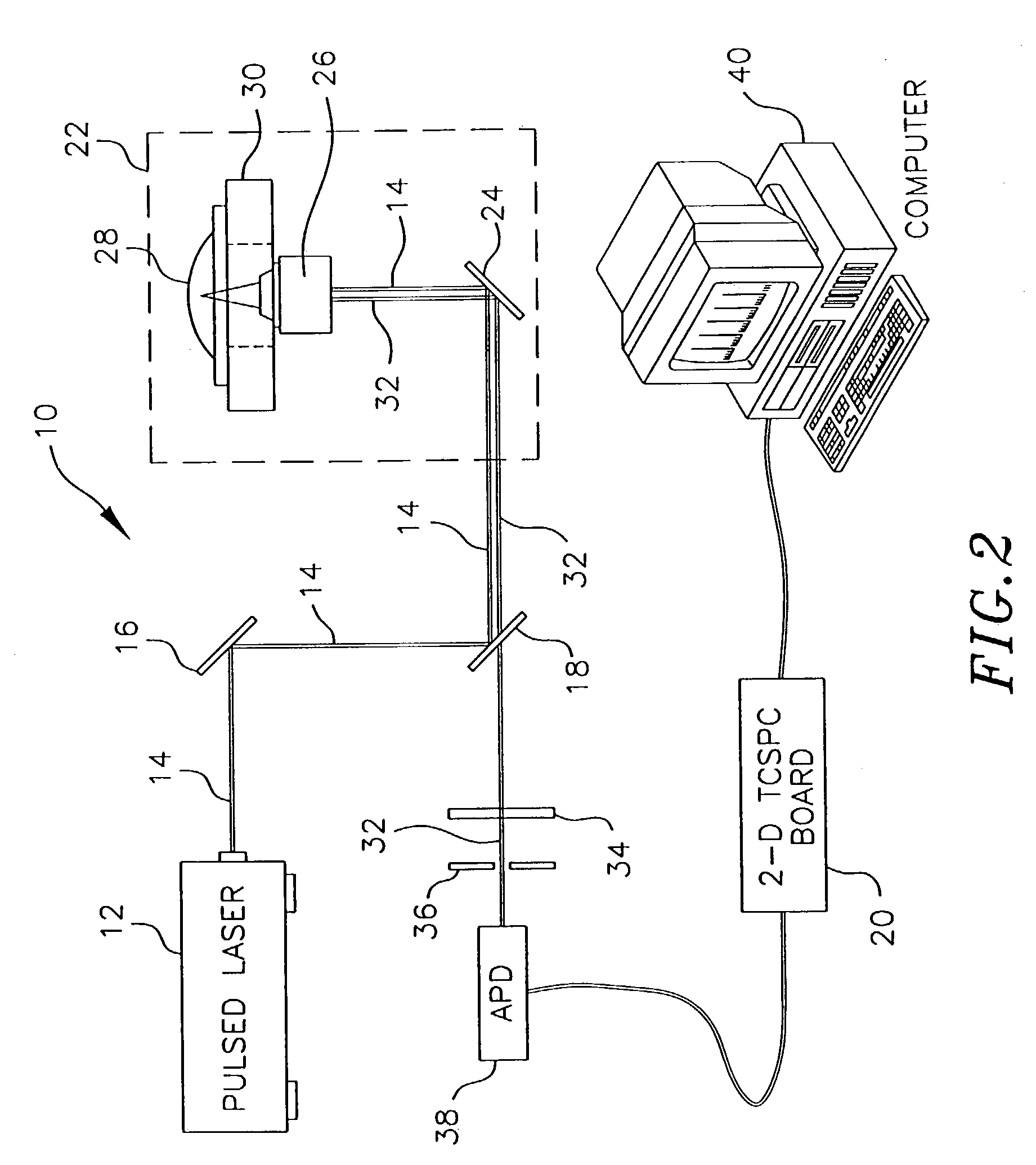
[0101]FIG. 8 shows time correlated data taken on a single cell of E. coli expressing red fluorescent protein (RFP) from the dsRED plasmid, available commercially from ClonTech Laboratories, Inc. (Palo Alto, Calif.). The trace was taken using an apparatus similar to the one shown in FIG. 2, but using a sample suspended in solution rather than on a solid substrate.

[0102]Specifically, a frequency doubled, pulse compressed, and mode locked Nd:YAG laser (532 nm, 10 psec) was used to excite the sample at a repetition rate of 82 MHz. To ensure proper beam quality and polarization, the light was passed through a single mode, polarization preserving glass fiber (F-SPA, Newport, Irvine, Calif.) and a polarizing beam splitter (05BC15PH.3, Newport, Irvine, Calif.). The laser light was delivered into an inverted, confocal microscope and reflected up towards the microscope objective with a dichroic mirro...

example 2

Light-Mediated Patterning in Cell Selection

[0107]The cationic porphyrin 5,10,15,20-Tetrakis [4-(trimethylammonio)phenyl]-21H,23H-porphine (TmaP), which has a maximum absorption at 412 nm wavelength, was added to a 3 mL liquid culture of E. coli in Luria Broth (LB) and the culture was incubated in the dark overnight. Approximately 50 uL of the culture was plated on an LB / TmaP agar plate, and portions of the plate was irradiated for about 2 minutes with visible light passed through a blue filter. The cells were then placed in an incubator and allowed to grow overnight at 37° C.

[0108]The image projected onto the plate is shown in FIG. 9A. As shown in FIG. 9B, those portions of the plate receiving visible light (the “white” portion of the image shown in FIG. 9A) show little or no growth. of E. coli, while portions of the plate receiving little or no visible light (the “black” portion of the image shown in FIG. 9A) show high density growth in the form of the Arizona State University masc...


PUM

PropertyMeasurementUnit
diameteraaaaaaaaaa
frequencyaaaaaaaaaa
diameteraaaaaaaaaa

Abstract

This invention provides a method for screening large numbers of individual cells or colonies of cells using scanning microscopy coupled with fluorescence lifetime measurement and analysis, using time-correlated single photon counting. This invention further provides an automated method for selecting cells that exhibit desired characteristics. The method uses the scanning microscope system to focus a laser beam onto a surface upon which cells are immobilized on the timescale of the procedure. The cells that are illuminated in this way are killed or their growth is inhibited. The focused laser beam is scanned across the surface and turned on and off during the scanning process such that only non-irradiated cells survive, resulting in a patterned cell growth This invention further provides a computer-controlled projection device, such as a micro-mirror array or a liquid crystal display system, which is sued to project an image onto the cells.

Description

CROSS-REFERENCE TO RELATED APPLICATIONS[0001]This application claims priority of International Application No. PCT / US01 / 24365, entitled SCANNING FLUORESCENCE LIFETIME MICROSCOPE: DIRECTED EVOLUTION, filed Aug. 2, 2001, which in turn claims priority to U.S. Provisional Application No. 60 / 222,691, filed Aug. 2, 2000, entitled COMPUTER INTERFACED SCANNING FLUORESCENCE LIFETIME MICROSCOPE APPLIED TO DIRECTED EVOLUTION METHODOLOGIES AND METHODS FOR LIGHT-MEDIATED PATTERNING IN CELL SELECTION, which are hereby incorporated by reference in their entirety.FIELD OF THE INVENTION[0002]The present invention relates generally to an apparatus and methods for rapidly and automatically screening and selecting cells exhibiting desirable physical traits and more specifically to a computer interfaced scanning fluorescence microscope applied to directed evolution methodologies and methods for light-mediated patterning in cell selection.BACKGROUND OF THE INVENTION[0003]Directed evolution is a process w...

Claims


Application Information

Patent Timeline
Patent Type & Authority Patents(United States)
IPC IPC(8): G01J3/30C12M1/34G01N21/64G01N33/533G01N33/567G02B21/16
CPCG01N21/6408G01N21/6428G01N21/6458G02B21/16G01N33/567G01N33/533G01N2021/6482
Inventor WOODBURY, NEAL W. T.BOWEN, BENJAMIN P.SCRUGGS, ALLAN
Owner ARIZONA STATE UNIVERSITY
Why Eureka
Try Eureka