
Powder for disks

a technology for powder and disks, applied in the field of powder for disks, can solve the problems of low hardness limit of nickel plating, failure of asperities and glide, asperities and glide failure, etc., to reduce the polish rate, increase the polish time/cost, and reduce the effect of planarization

Inactive Publication Date: 2007-04-10
HITACHI GLOBAL STORAGE TECH NETHERLANDS BV
View PDF16 Cites 2 Cited by
  • Summary
  • Abstract
  • Description
  • Claims
  • Application Information

AI Technical Summary

Benefits of technology

[0019]In an exemplary aspect of the invention, glass disks are transported, for example from the glass manufacturer to the end user, in a stack. The stack provides for a compact shipping arrangement, and helps to protect the disks from breakage during transport.
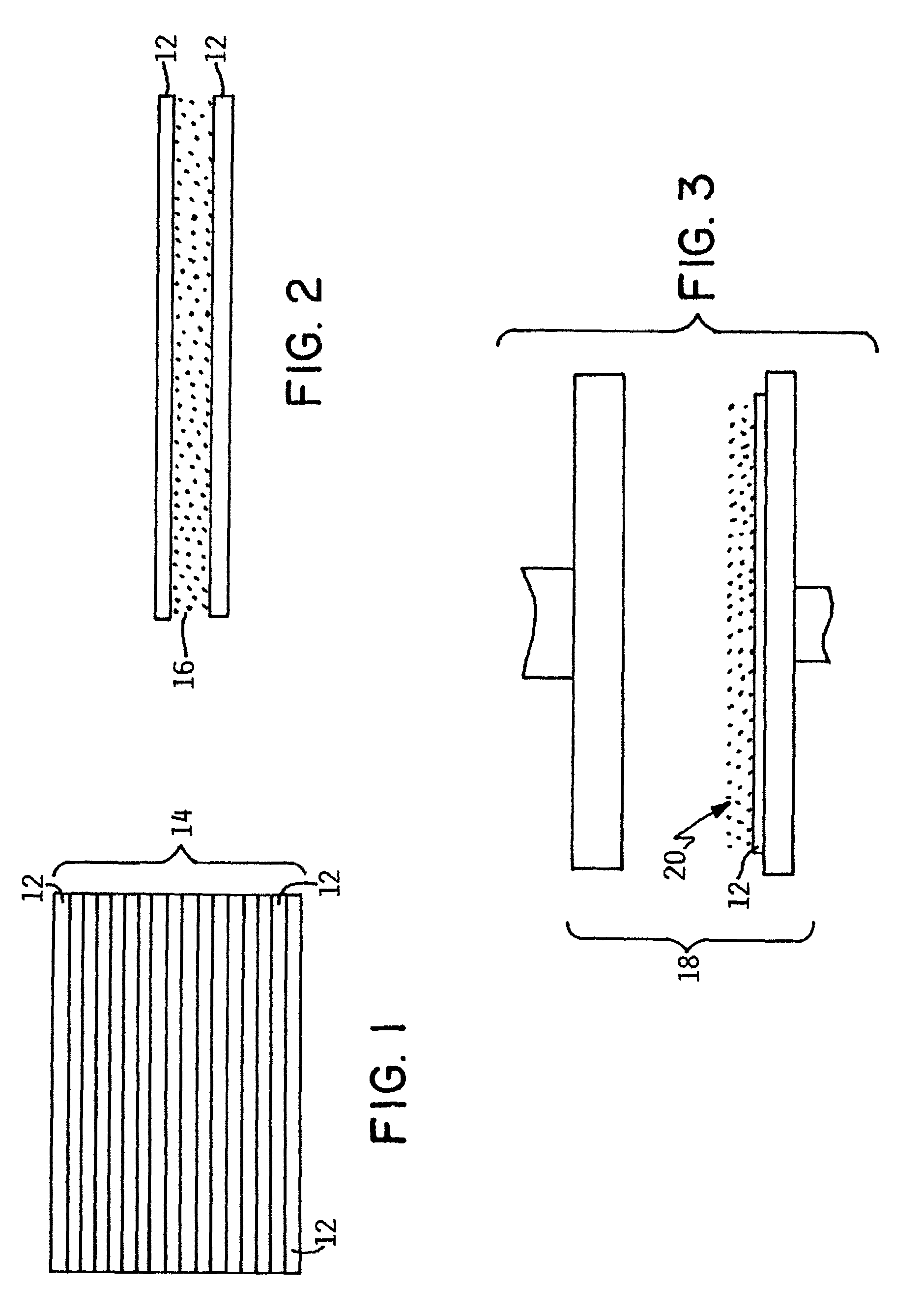
[0020]To prevent a disk from being damaged, for example by scratching an adjacent disk of the stack, and to facilitate the separation of the disks from each other, a powder is disposed between the adjacent disks. The powder coats a surface of the respective disks, so that the surface of one disk is spaced apart from the surface of an adjacent (superposed) disk using only the powder. The powder serves as a cushion between the disks, so that the disks will not damage one another. Moreover, the powder may absorb impacts to the stack caused by improper handling, thus protecting the disks from breakage. Further, the use of the powder will allow some spacing between the adjacent disks, preventing close forces of attraction as polarization and coulombic forces, from holding the disks together, thus facilitating the separation of the disks from the stack of disks.
[0022]In an exemplary aspect of the invention, the powder is an inorganic material, such as an inorganic mineral. Inorganic powders have several advantageous characteristics as compared to organic powders. For example, organic powders cause reduced polish rates by acting as a lubricant between the pad / slurry and the glass which decreases planarization and increases polish time / costs. Moreover, since the polishing slurry is typically recirculated and reused, the concentration of the organic powder will increase within the slurry over time, shortening slurry life. Thus, the use of an inorganic powder will reduce any cumulative adverse effects, allowing the slurry to be used for as long a period of time as is standard practice with current manufacturing.
[0024]In a further aspect of the invention, the powder is calcium carbonate. Alternatively, other powders that exhibit similar suitable properties may be used. For example, the powder could be selected from the group including calcium carbonate, calcium magnesium carbonate, calcium phosphate, magnesium carbonate, magnesium borate, magnesium oxide, magnesium phosphate, and clay. These materials are relatively inert, have a pH of 7–12, and are safe to use. Moreover, the presence of a powder composed of these materials on a disk will not adversely affect the subsequent polishing process by such things as scratching or lubricating. Additionally, these powders are readily available, and can be purchased from a variety of sources.
[0025]In a further exemplary aspect of the invention, the powder has a grain size of about a 200 mesh. Such a size powder can be easily dispersed in the slurry, and will be large enough to serve as a spacer and cushion to the disks.

Problems solved by technology

However, aluminum is relatively soft, so when it is handled, it is possible to ding the disk and form an area where data can not be retrieved from.
However, the nickel plating has a low limit in hardness and has a tendency to become magnetic from composition or heating in sputter at temperatures greater than 300° C., causing errors in reading and writing to the disk.
Additionally, while aluminum disks can be made smooth, their surfaces are very easily damaged during disk manufacturing or file build causing asperities and glide failures.
However, the use of such paper is problematic to the end user.
Nevertheless, it is relatively common for some of the paper to end up in undesired locations, such as caught in the workings of an expensive piece of manufacturing equipment causing possible equipment damage and loss of thru-put, or as debris on the floor.
However, the paper will often fall off the disk at a non-desired location, such as in the final process cassette, causing manufacturing problems discussed above.
Moreover, occasionally more than one piece of paper will be erroneously placed between two adjacent stacked disks.
This could cause the remaining paper to be moved into subsequent processing areas together with the disk, or the paper could be misidentified as the next disk, resulting in machine malfunctions.
However, if any paper remains on the surface of the disk, the disk-moving mechanism may erroneously identify the paper as being a disk, and attempt to move the paper, rather than the disk, to further processing stations.
As will be appreciated, the presence of undesired paper can thus cause subsequent problems, including down time of the disk preparation processes, reduced productivity, and unnecessary expenses.

Method used


Image

  • Powder for disks
  • Powder for disks

Examples


Embodiment Construction

[0029]The invention will now be described in more detail by way of example with reference to the embodiments shown in the accompanying figures. It should be kept in mind that the following described embodiments are only presented by way of example and should not be construed as limiting the inventive concept to any particular physical configuration.

[0030]Further, if used and unless otherwise stated, the terms “upper”, “lower”, “front”, “back”, “over”, “under”, and similar such terms are not to be construed as limiting the invention to a particular orientation. Instead, these terms are used only on a relative basis.

[0031]The present invention is directed toward disks, such as glass or glass-ceramic disks used as data storage devices in disk drives. By way of example, the glass disks are formed from alumino-silicate glass. Further, the disks typically are standardized in diameter. For example, the current conventional disks have one of a diameter of 65, 70, 84, or 95 millimeters, for ...


PUM

PropertyMeasurementUnit
temperaturesaaaaaaaaaa
diameteraaaaaaaaaa
diameteraaaaaaaaaa

Abstract

A plurality of disks include a first disk and a second disk stacked upon the first disk. The first disk and the second disk are each formed from glass or glass-ceramic. A powder is disposed between the first disk and the second disk. The powder is selected from the group including calcium carbonate, calcium magnesium carbonate, calcium phosphate, magnesium carbonate, magnesium borate, magnesium oxide, magnesium phosphate, and clay.

Description

BACKGROUND OF THE INVENTION[0001]1. Field of the Invention[0002]The invention relates to a powder for disks, such as glass disks used in storage devices, and in particular to a powder for separating and cushioning stacked glass disks.[0003]2. Background Information[0004]Circular-shaped magnetic disks are typically used in hard disk drives of computers, for example, for use in data storage applications. Such magnetic disks may be formed from aluminum or from glass, for example, and will typically have a magnetic surface coating located thereon. A head of the disk drive interacts with the magnetic surface coating to read and write information to the disk. Such magnetic disks have achieved storage capacities of several gigabytes or more, using current technology.[0005]Typically, the head of the disk drive that reads and writes information to the disk is arranged to fly a small distance above a surface of the disk. By bringing the head closer to the surface of the disk, higher density r...

Claims


Application Information

Patent Timeline
Patent Type & Authority Patents(United States)
IPC IPC(8): B24B1/00B05D1/02B65B33/00B24B37/04G11B5/73G11B5/84
CPCB24B37/0056B24B37/04G11B5/7315G11B5/8404Y10T428/15Y10T29/49812Y10T428/2457G11B5/73921
Inventor MCCAFFREY, PATRICK MICHAELPILTINGSRUD, DOUGLAS HOWARD
Owner HITACHI GLOBAL STORAGE TECH NETHERLANDS BV
Learn More