Single-wall carbon nanotubes from high pressure CO

a carbon nanotube, high-pressure technology, applied in the direction of transportation and packaging, pressurized chemical process, energy-based chemical/physical/physical-chemical process, etc., can solve the problems of inherently costly, high energy consumption, and heterogeneous product of nanotubes

Inactive Publication Date: 2007-04-17
RICE UNIV
View PDF24 Cites 104 Cited by
  • Summary
  • Abstract
  • Description
  • Claims
  • Application Information

AI Technical Summary

Benefits of technology

[0020]The SWNT products can be separated from the gaseous stream and recovered. The gaseous stream, which is primarily unreacted CO can be recovered and recycled. The resulting SWNT products are substantially pure (99%) and can be used without complicated separation and purification

Problems solved by technology

Although the laser vaporization process produces improved single-wall nanotube preparations, the product is still heterogeneous, and the nanotubes are too tangled for many potential uses of these materials.
In addition, the vaporization of carbon is a high energy process and is inherently costly.
Their yield is intrinsically limited due to rapid surrounding of the catalyst particles and the alumina particle that supports them by a dense tangle of single-wall carbon nanotubes.
Removal of the underlying alumina suppor

Method used


Image

  • Single-wall carbon nanotubes from high pressure CO
  • Single-wall carbon nanotubes from high pressure CO
  • Single-wall carbon nanotubes from high pressure CO

Examples


example 1

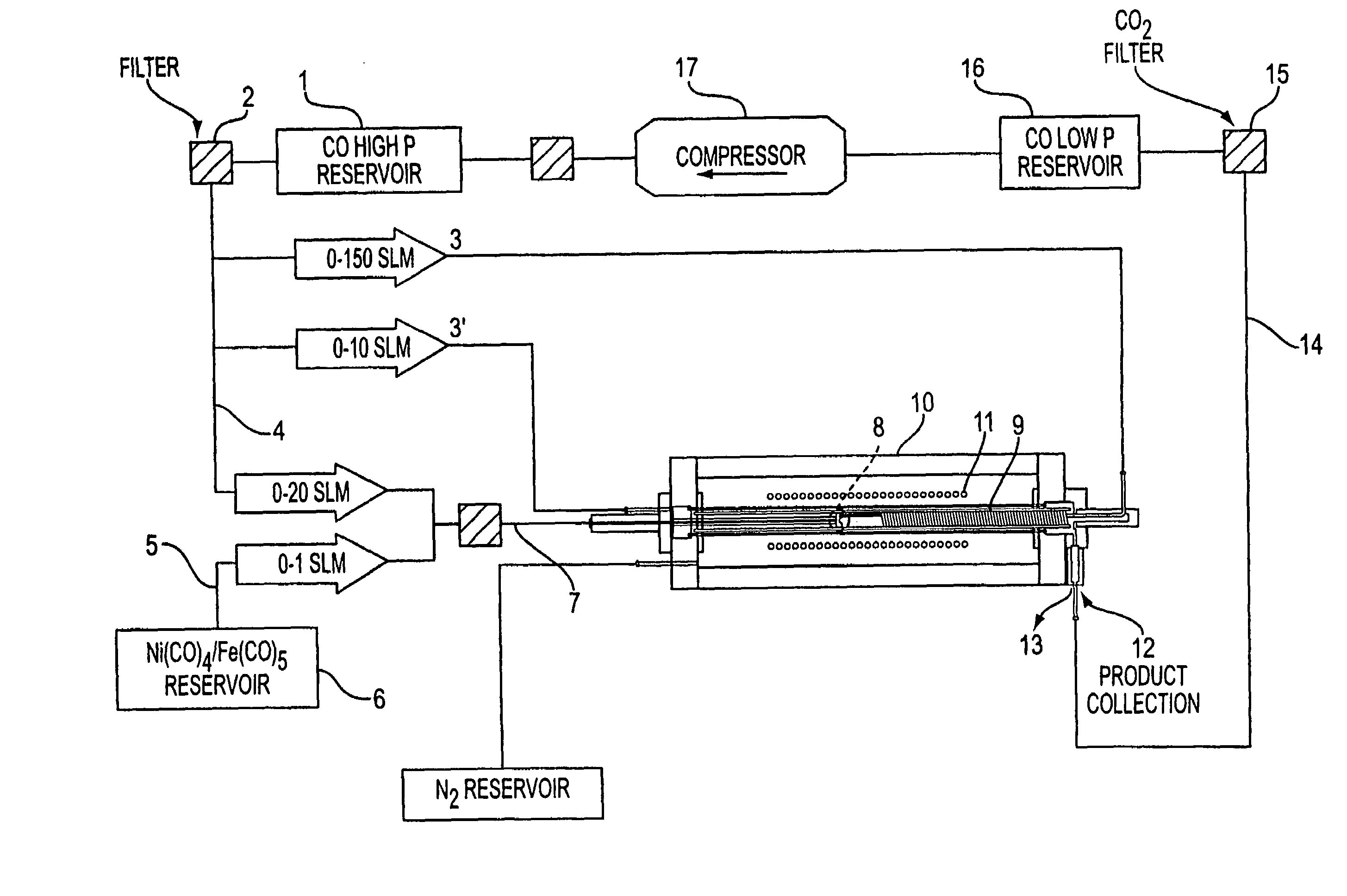
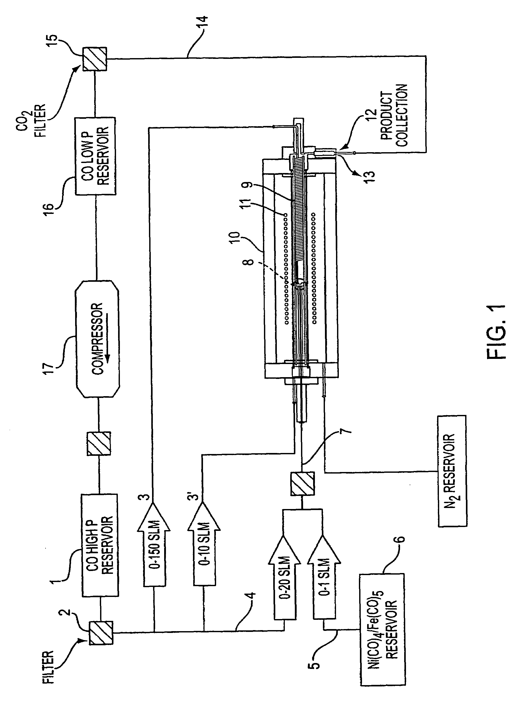
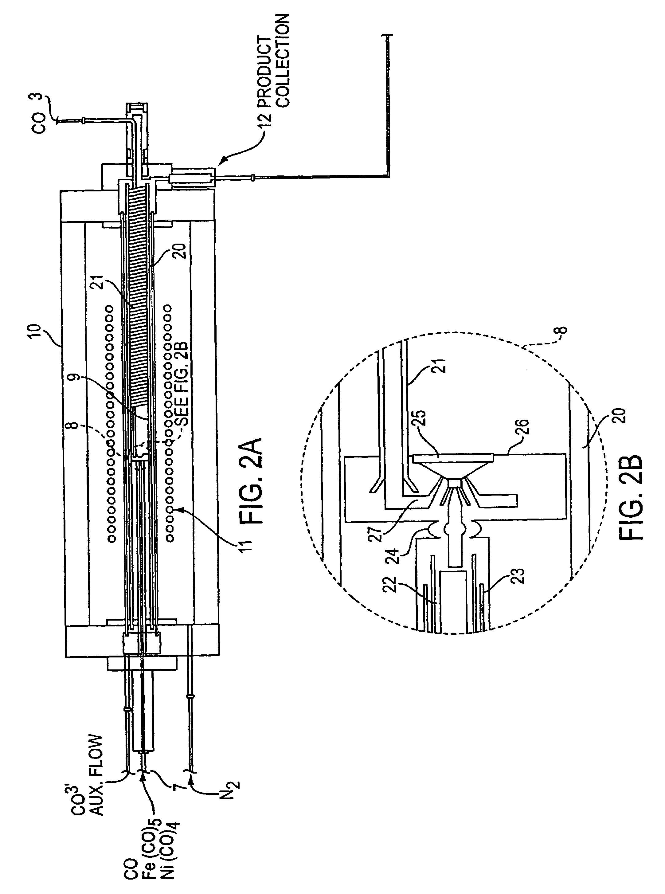
[0069]This Example employed the apparatus shown in FIGS. 1 and 2 and demonstrates the process of the present invention is useful to produce clean SWNTs of small diameter.

Summary of Conditions:

[0070]

Operating Pressure: 600 psi (40 atmospheres) of COOperating Temp.900° C.

Flow Conditions:

[0071]Two standard liters per minute (slm) of CO containing 0.5 Torr of Fe(CO)5 were passed through the air-cooled injector. 8 slm of pure CO were preheated in the copper heating coil, and passed through the stainless steel injector manifold. The two flows were mixed in the mixing zone and the combined gases passed through the growth and annealing zone and into the product recovery zone.

[0072]Run time: 2 hours

[0073]Results:

[0074]17.5 mg of material was collected from the product recovery zone at the exit of the high pressure reactor. SEM measurements showed that this material was primarily SWNT. EDX and TGA measurements showed that this material contained 3–5 atom % of iron. TEM measurements showed tha...

example 2

[0075]Using the same apparatus as in Example 1, this Example demonstrates that Ni(CO)4 does not exhibit appreciable catalytic effects under the preferred higher pressure CO process conditions.

[0076]Summary of Conditions:

[0077]

Operating Pressure: 450 psi (30 atmospheres) of COOperating Temp.1000° C.

Flow Conditions:

[0078]2.5 standard liters per minute (slm) of CO containing 0.4 Torr of Ni(CO)4 were passed through the air-cooled injector. 7.5 slm of pure CO were preheated in the copper heating coil, and passed through the stainless steel injector manifold. The two flows were mixed in the mixing zone and the combined gases passed through the growth and annealing zone and into the product recovery zone.

[0079]Run time: 2 hours

[0080]Results:

[0081]Powdery material was collected from the product recovery zone at the exit of the high pressure reactor. This material was not weighed. SEM measurements showed that this material contained no SWNT; it was composed of metal particles overcoated with...

example 3

[0082]Again using the apparatus of Example 1, this Example shows that employing Ni(CO)4 as a nucleating agent substantially improves the productivity of the high pressure CO process.

Summary of Conditions:

[0083]

Operating Pressure: 450 psi (30 atmospheres) of COOperating Temp.1000° C.

Flow Conditions:

[0084]2.5 standard liters per minute (slm) of CO containing 0.2 Torr of Fe(CO)5 and 0.2 Torr of Ni(CO)4 were passed through the air-cooled injector. 7.5 slm of pure CO were preheated in the copper heating coil, and passed through the stainless steel injector manifold to the mixing zone where it was combined with the injector flow. The combined gases passed through the growth and annealing zone into the product recovery zone.

[0085]Run time: 2 hours

[0086]Results:

[0087]20.1 mg of material was collected from the product recovery zone at the exit of the high pressure reactor. SEM measurements showed that this material was primarily SWNT. EDX measurements showed that this material contained 1.2 ...


PUM


Abstract

The present invention discloses the process of supplying high pressure (e.g., 30 atmospheres) CO that has been preheated (e.g., to about 1000° C.) and a catalyst precursor gas (e.g., Fe(CO)5) in CO that is kept below the catalyst precursor decomposition temperature to a mixing zone. In this mixing zone, the catalyst precursor is rapidly heated to a temperature that results in (1) precursor decomposition, (2) formation of active catalyst metal atom clusters of the appropriate size, and (3) favorable growth of SWNTs on the catalyst clusters. Preferably a catalyst cluster nucleation agency is employed to enable rapid reaction of the catalyst precursor gas to form many small, active catalyst particles instead of a few large, inactive ones. Such nucleation agencies can include auxiliary metal precursors that cluster more rapidly than the primary catalyst, or through provision of additional energy inputs (e.g., from a pulsed or CW laser) directed precisely at the region where cluster formation is desired. Under these conditions SWNTs nucleate and grow according to the Boudouard reaction. The SWNTs thus formed may be recovered directly or passed through a growth and annealing zone maintained at an elevated temperature (e.g., 1000° C.) in which tubes may continue to grow and coalesce into ropes.

Description

RELATED APPLICATIONS[0001]This application is a division of co-pending prior division application Ser. No. 09 / 830,642, filed Jul. 1, 2002, which is the 35 U.S.C. § 371 national application of International Application Number PCT / US99 / 25702 filed on Nov. 3, 1999, which designated the United States, claiming priority to provisional U.S. patent application Ser. Nos. 60 / 106,917, filed on Nov. 3, 1998; 60 / 114,588, filed Dec. 31, 1998; 60 / 117,287, filed Jan. 26, 1999; and 60 / 161,728, filed Oct. 27, 1999.BACKGROUND OF THE INVENTION[0002]1. Field of the Invention[0003]This invention relates generally to the production of single-wall nanotubes; in particular, to gas-phase nucleation and growth of single-wall carbon nanotubes from high pressure CO.[0004]2. Description of Related Art[0005]Fullerenes are closed-cage molecules composed entirely of sp2-hybridized carbons, arranged in hexagons and pentagons. Fullerenes (e.g., C60) were first identified as closed spheroidal cages produced by conden...

Claims


Application Information

Patent Timeline
IPC IPC(8): C01B11/02B01J3/04B01J19/12B01J19/26C01B31/02D01F9/127
CPCB01J3/04B01J19/121B01J19/26B82Y30/00B82Y40/00C01B31/0233D01F9/1278B01J4/002B01J3/042Y10T428/30B01J2219/0875C01B2202/02Y10S977/75C01B2202/36Y10S977/845Y10S977/843Y10S977/751Y10S977/951C01B32/162C01B32/05B82B3/00
Inventor SMALLEY, RICHARD E.SMITH, KEN A.COLBERT, DANIEL T.NIKOLAEV, PAVELBRONIKOWSKI, MICHAEL J.BRADLEY, ROBERT K.ROHMUND, FRANK
Owner RICE UNIV
Why Eureka
Try Eureka