Objective lens, optical element, optical pick-up apparatus and optical information recording and/or reproducing apparatus equipped therewith

a technology of optical information recording and/or reproducing apparatus, which is applied in the direction of lenses, optical beam sources, instruments, etc., can solve the problems of increasing the size of the optical pick-up system, increasing production costs, and difficulty in ensuring the sufficient working distance when the cd is recorded, and achieves fine conductivity and high diffraction efficiency.

Active Publication Date: 2007-04-17
KONICA CORP
View PDF3 Cites 57 Cited by
  • Summary
  • Abstract
  • Description
  • Claims
  • Application Information

AI Technical Summary

Benefits of technology

[0023]Further, the object of the present invention is to provide the optical pick-up apparatus by which the mutual compatibility of three kinds of optical disks of the high density DVD, DVD, and CD is attained by using the objective lens common to the diffraction optical element, and the optical pick-up apparatus in which the utilization efficiency of a sufficient light amount can be obtained in the using wavelength region of respective optical disks.
[0243]Further, it is preferable that at least 2 of the substrate thickness difference correcting means, substrate thickness error correcting means, chromatic aberration correcting means, and aperture regulation / changing means are integrated. When being integrated in this manner, the number of parts can be reduced, and the optical pick-up apparatus can be compactly structured, and it can contributes to the cast reduction.

Problems solved by technology

As a means to attain the compatibility, it can be considered that the objective lenses corresponding to the standard of respective optical disks are mechanically switched, or the optical pick-up apparatus corresponding to the standard of respective optical disks are mounted, however, in this case, the switching mechanism of the objective lens or a plurality of optical pick-up apparatus are necessary, resulting in the increase of the size of the optical pick-up system, the increase of the number of parts, and the increase of the production cost.
On the other hand, because the working distance of the objective lens of 2-group composition is shorter than that of the conventional objective lens of 1 group composition, it is very difficult to secure the sufficient working distance when the CD is recorded and reproduced.
Accordingly, in order to prevent the breakage of the data by the collision of the CD and objective lens, it is necessary to sufficiently secure the working distance when the CD is recorded and reproduced, and from this point of view, in the optical pick-up system by which recording and reproducing are conducted by using the common objective lens onto 3 kinds of optical disks whose standards are different, it can be said that the objective lens of 2-group composition is undesirable.
However, in the conventional refraction type objective lens, because, by the dispersion of the lens material, the spherical aberration is changed, it is difficult that the light flux from the light source having the different wavelength is converged in almost no-aberration onto the information recording surfaces of respective optical disks.
However, in the optical pick-up apparatus, by the reduction of the wavelength of the light source and the increase of the NA of the objective lens, the problems which will be described below, are actualized.
The first problem is a chromatic aberration generated in the objective lens when the blue violet semiconductor laser generating the short wavelength of about 400 nm is used as the light source.
Because the mode hopping is a wavelength change caused instantaneously in such a manner that the focusing mechanism of the objective lens can not follow it, when the chromatic aberration of the objective lens is not corrected, the de-focus component corresponding to the movement amount of the image formation position is added, thereby the light converging performance of the objective lens is deteriorated.
Therefore, in the high density DVD, when the blue violet semiconductor laser is used as the light source, the light converging performance of the objective lens is largely changed when the light source occurs mode hopping, thereby, there is a possibility that the stable recording or reproducing can not be conducted.
The second problem is a problem of the spherical aberration generated by various error factors when NA of the objective lens is increased.
In order to suppress this spherical aberration within the allowance, it is necessary that the tolerance to the production error of the protective substrate thickness of the optical disk is made several μm, however, in this case, the yield of the production of the optical disk is lowered, and there is a possibility that the mass production can not be attained.
When the environmental temperature of the objective lens formed of the plastic material rises and the refractive index of the objective lens is changed, in the objective lens, the spherical aberration is deteriorated.

Method used


Image

  • Objective lens, optical element, optical pick-up apparatus and optical information recording and/or reproducing apparatus equipped therewith
  • Objective lens, optical element, optical pick-up apparatus and optical information recording and/or reproducing apparatus equipped therewith
  • Objective lens, optical element, optical pick-up apparatus and optical information recording and/or reproducing apparatus equipped therewith

Examples


first embodiment

(First Embodiment)

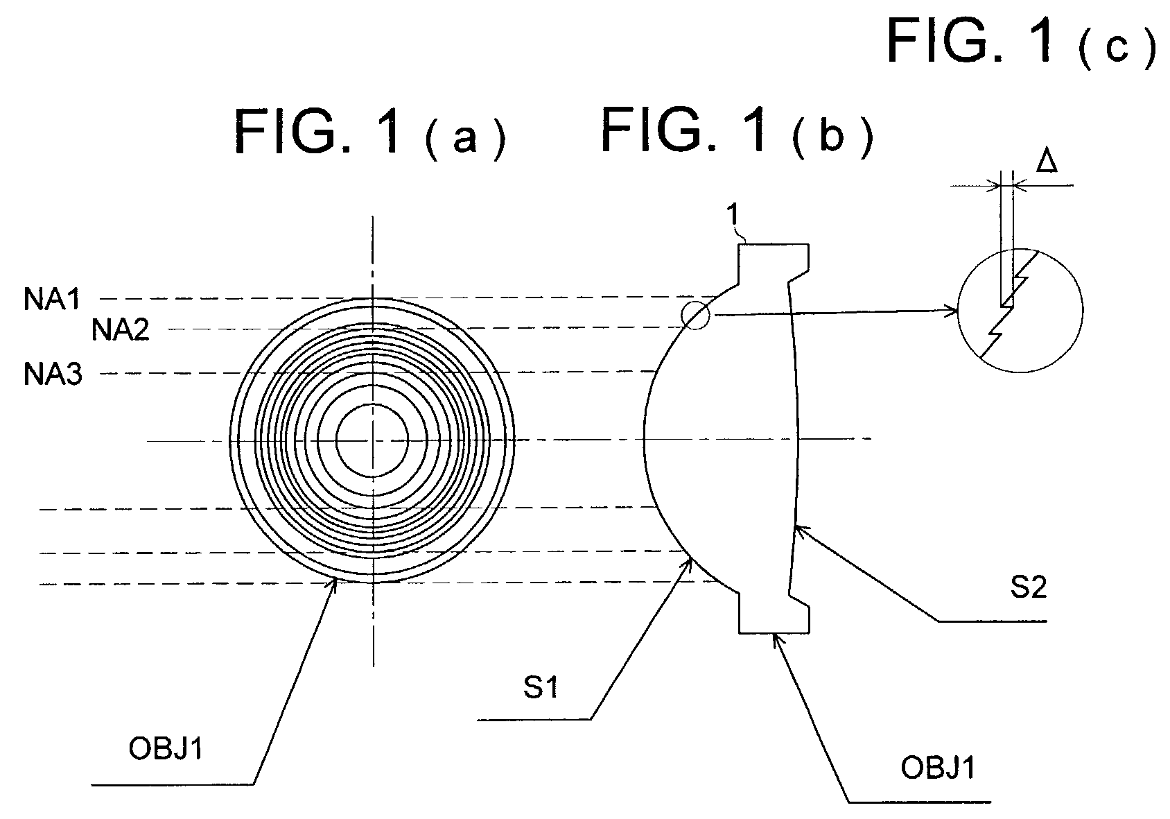
[0350]FIG. 1 is a schematic diagram showing objective lens OBJ1 of the present embodiment, and FIG. 1(A) is a front view, FIG. 1(B) is a side view and FIG. 1(C) is a diagram wherein a side face is partially enlarged. This objective lens OBJ1 is an objective lens that is common to, for example, a high density optical disk such as a high density DVD using a short wavelength light source like a violet semiconductor laser, an optical disk meeting the DVD standard requirements such as DVD, DVD-ROM, DVD-RAM, DVD-R, DVD-RW, and DVD+RW which use a red semiconductor laser, and an optical disk meeting the CD standard requirements such as CD, CD-R, CD-RW, CD-Video and CD-ROM which use an infrared semiconductor laser, and it is applied to an optical pickup device for recording / reproducing compatibly, and has a function to converge a laser beam emitted from the light source on an information recording surface of the optical disk.

[0351]The objective lens OBJ1 is a single lens ha...

second embodiment

(Second Embodiment)

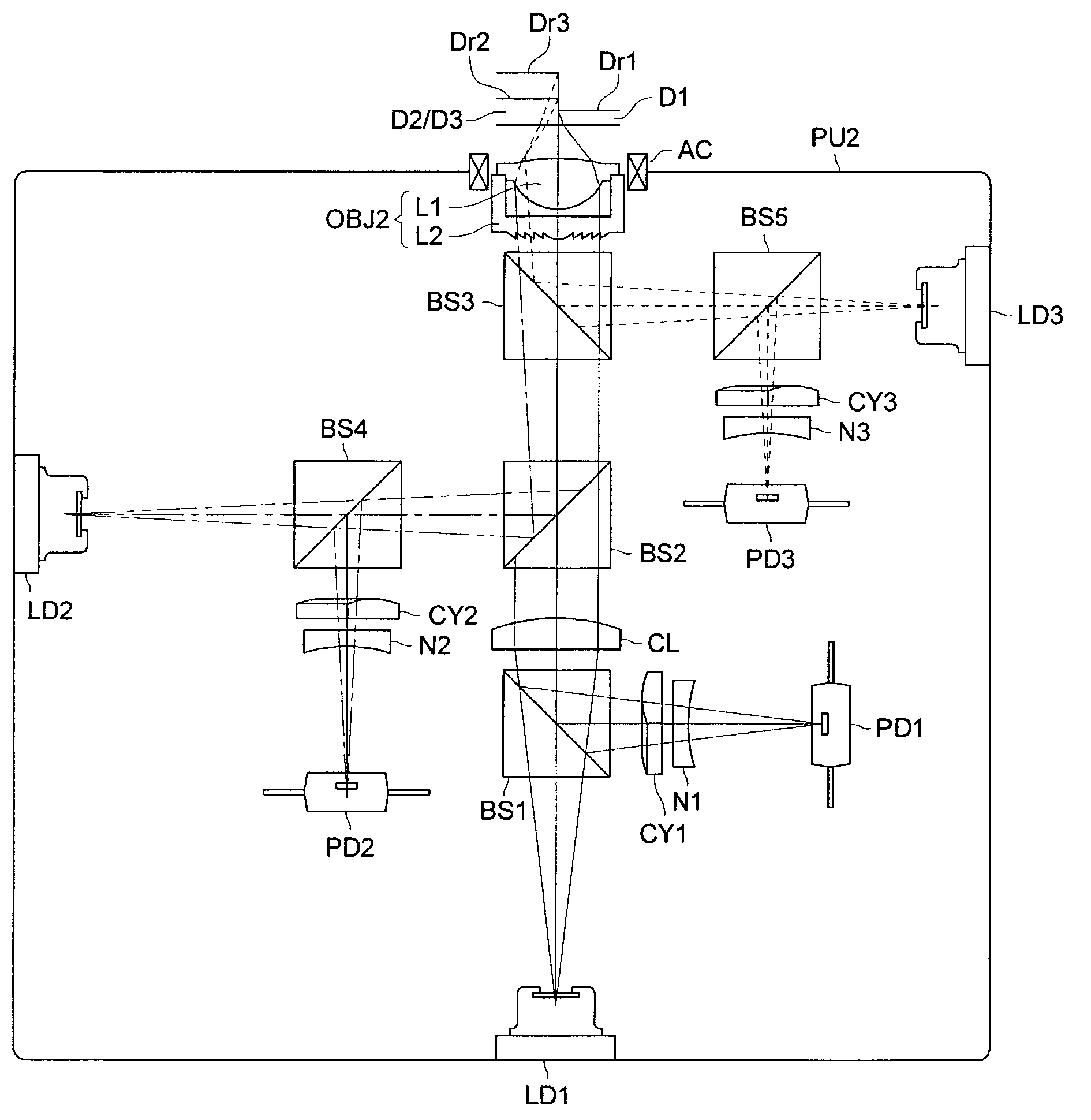
[0391]FIG. 3 is a schematic diagram showing objective lens OBJ2 of the present embodiment, and FIG. 3(A) is a front view, FIG. 3(B) is a side view and FIG. 3(C) is a diagram wherein a side face is partially enlarged. This objective lens OBJ1 is an objective lens that is common to, for example, a high density optical disk such as a high density DVD using a short wavelength light source like a violet semiconductor laser, an optical disk meeting the DVD standard requirements such as DVD, DVD-ROM, DVD-RAM, DVD-R, DVD-RW, and DVD+RW which use a red semiconductor laser, and an optical disk meeting the CD standard requirements such as CD, CD-R, CD-RW, CD-Video and CD-ROM which use an infrared semiconductor laser, and it is applied to an optical pickup device for recording / reproducing compatibly, and has a function to converge a laser beam emitted from the light source on an information recording surface of the optical disk.

[0392]The objective lens OBJ2 is a hybrid object...

example 1

[0411]Example 1 wherein lens data are shown in Table 1 is a plastic single lens that is appropriate as objective lens OBJ1 in the embodiment stated above, and a diffractive structure in a form of ring-shaped zones is formed on the first surface (S1). In the objective lens of the present example, the following is assumed as specifications for the first optical disk D1, the second optical disk D2 and the third optical disk D3.

[0412]NA1=0.85, λ1=405 nm, t1=0.1 mm, m1=0

[0413]NA2=0.65, λ2=650 nm, t2=0.6 mm, m2=−0.03

[0414]NA3=0.50, λ3=780 nm, t3=1.2 mm, m3=−0.14

[0415]Optimized wavelength λB and optimized order nB of the diffractive structure formed in the common area corresponding to the inside of NA3 and the first peripheral area corresponding to the inside of NA3–NA2 are respectively λB=415 nm and nB=6, and optimized wavelength λB and optimized order nB of the diffractive structure formed in the second peripheral area corresponding to the inside of NA2-NA1 are respectively λB=405 nm and...


PUM

PropertyMeasurementUnit
thickness t1aaaaaaaaaa
thickness t2aaaaaaaaaa
thickness t3aaaaaaaaaa

Abstract

A hybrid objective lens has a refractive lens and a diffractive optical element constructed by plural coaxial ring-shaped zones on at least one optical surface thereof. When n1, n2 and n3 each is a diffraction order of a diffracted ray having a maximum light amount among diffracted rays of each of first, second and third light flux having wavelength λ1, λ2 and λ3 when respective light flux comes to be incident into the diffractive structure respectively, the following formulas are satisfied:|n1|>|n2|, and |n1|>|n3|, andthe hybrid objective lens converges a n1-th, n2-th and n3-th order diffracted ray of the first, second and third light flux onto an information recording plane of each of the first, second ant third optical information recording medium respectively so as to form an appropriate wavefront within respective prescribed necessary image side numerical apertures.

Description

BACKGROUND OF THE INVENTION[0001]The present invention relates to an optical pick-up apparatus by which at least one of the recording and reproducing of the information can be conducted for 3 kinds of the optical information recording media whose standards (recording density) are different, objective lens which can be used for the optical pick-up apparatus, substrate thickness difference correcting means, chromatic aberration correcting means, substrate thickness error correcting means, aperture regulating / changing means, optical element and a recording•reproducing apparatus using this optical pick-up apparatus.[0002]Conventionally, the optical disk is, as well known in CD (Compact Disk) or DVD (Digital Versatile Disc), widely used for the storage of the digital data such as the accumulation of the music information and image information, or storage of the computer data. In such a situation, recently, together with the arrival of an information-oriented society, the increase of capa...

Claims


Application Information

Patent Timeline
Patent Type & Authority Patents(United States)
IPC IPC(8): G11B7/00G02B3/08G02B13/18G11B7/125G11B7/1275G11B7/1353G11B7/1372G11B7/1374G11B7/139G11B7/1392
CPCG11B7/1275G11B7/1353G11B7/1374G11B7/139G11B7/13925G11B2007/0006G11B2007/13727
Inventor KIMURA, TOHRUSAKAMOTO, KATSUYAATARASHI, YUICHI
Owner KONICA CORP
Why Eureka
Try Eureka