Biocompatible bonding method and electronics package suitable for implantation

a biocompatible bonding and electronics package technology, applied in the direction of printed circuit, printed element electric connection formation, therapy, etc., can solve the problems of biocompatible connection, high number of stimulation electrodes cannot be achieved without sacrifice, and each of these materials has limitations on its use as implants

Active Publication Date: 2007-05-01
SECOND SIGHT MEDICAL PRODS +1
View PDF10 Cites 92 Cited by
  • Summary
  • Abstract
  • Description
  • Claims
  • Application Information

AI Technical Summary

Benefits of technology

[0015]A method of making an implantable electronic device comprising depositing a release coat on a hybrid substrate, depositing a first flexible electrically insulating substrate on the release coat; depositing an electrically conducting metal layer on the first flexible electrically insulating substrate, depositing a second flexible electrically insulating substrate on the metal layer, cutting said hybrid substrate to distinguish a...

Problems solved by technology

Packaging of a biomedical device intended for implantation in the eye, and more specifically for physical contact with the retina, presents a unique interconnection challenge.
It is possible to fabricate a suitable electrode array using discrete wires, but with this approach, a high number of stimulation electrodes cannot be achieved without sacrificing cable flexibility (to a maximum of about 16 electrodes).
However, none of these methods results in a biocompatible connection.
Each of these materials has limitations on its use as an implant.
Indium corrodes when placed in a saline environment.
Gold, although relatively inert and biocompatible, migrates in a saline solution, when electric current is passed through it, resulting in unreliable connections.
However, encapsulation proves difficult to effectively implement with...

Method used


Image

  • Biocompatible bonding method and electronics package suitable for implantation
  • Biocompatible bonding method and electronics package suitable for implantation
  • Biocompatible bonding method and electronics package suitable for implantation

Examples


Embodiment Construction

[0034]The following description is the best mode presently contemplated for carrying out the invention. This description is not to be taken in a limiting sense, but is made merely for describing the general principles of the invention. The scope of the invention should be determined with reference to the claims.

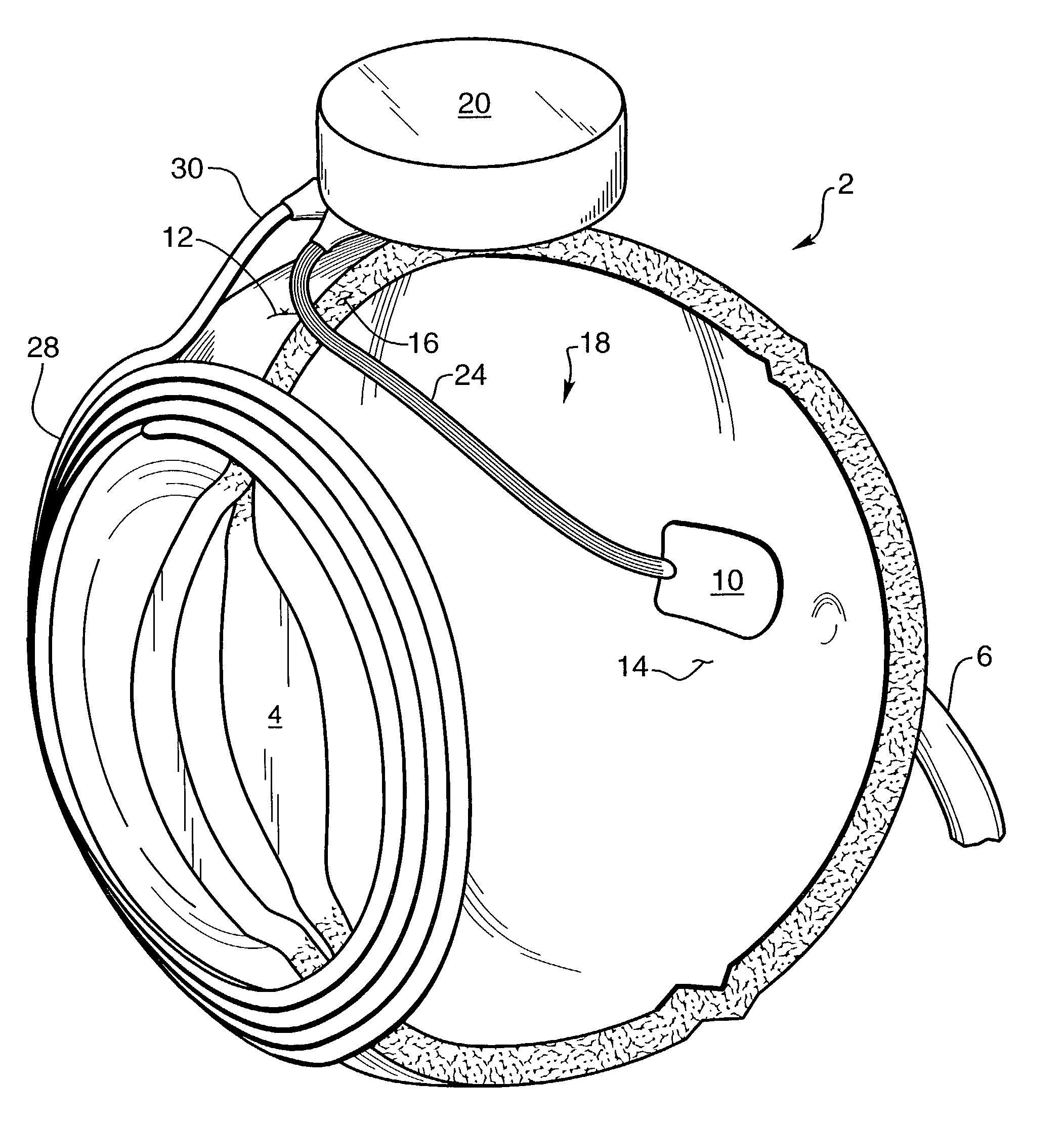
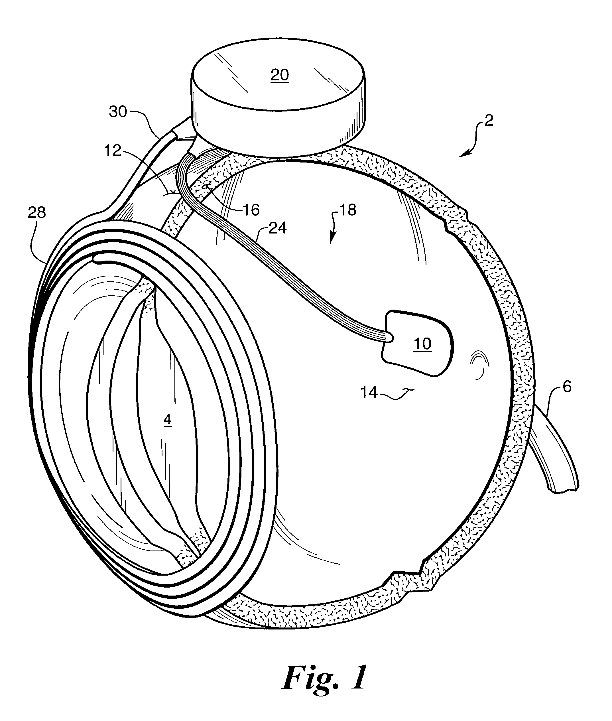
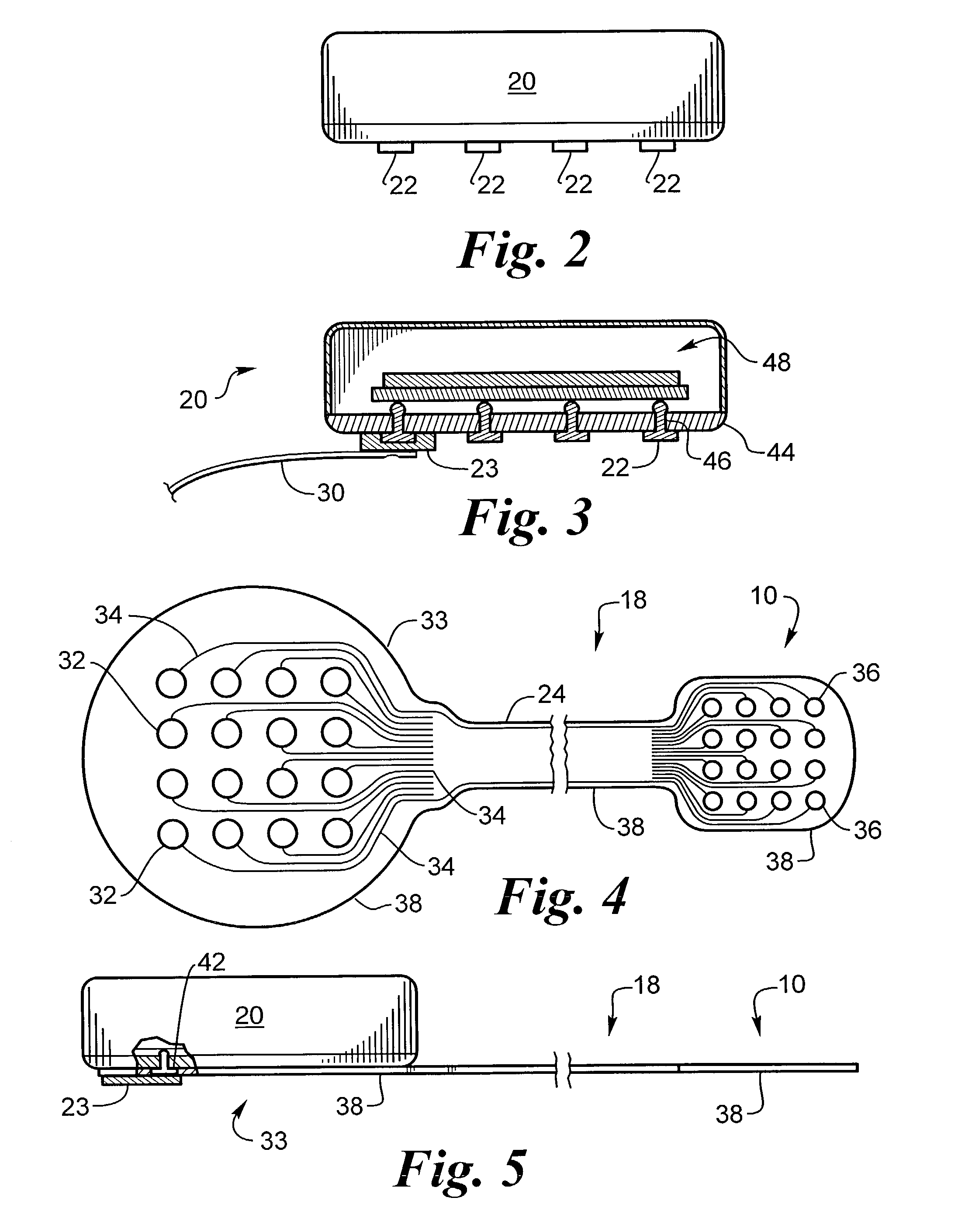
[0035]The present invention provides a flexible circuit electronics package and a method of bonding a flexible circuit to a hermetic integrated circuit which is useful for a number of applications, including implantation in living tissue as a neural interface, such as a retinal electrode array or an electrical sensor. The tissue paper thin flexible circuit 18, FIG. 1, transmits electrical signals to the eye 2 by means of electrodes, that are located in a stimulating electrode array 10, that are in contact with the retina 14. It is obvious that in addition to a stimulating electrode array or sensing electrode, the electrodes may be contacts connecting to remote electrodes. FIG...


PUM

PropertyMeasurementUnit
Electrical conductivityaaaaaaaaaa
Flexibilityaaaaaaaaaa
Biocompatibilityaaaaaaaaaa

Abstract

The invention is directed to a method of bonding a hermetically sealed electronics package to an electrode or a flexible circuit and the resulting electronics package, that is suitable for implantation in living tissue, such as for a retinal or cortical electrode array to enable restoration of sight to certain non-sighted individuals. The hermetically sealed electronics package is directly bonded to the flex circuit or electrode by one of several methods, including attachment by an electrically conductive adhesive, such as epoxy or polyimide, containing platinum metal flake in biocompatible glue; diffusion bonding of platinum bumps covered by an insulating layer; thermal welding of wire staples; or an integrated interconnect fabrication. The resulting electronic device is biocompatible and is suitable for long-term implantation in living tissue.

Description

[0001]This application claims the benefit of U.S. Provisional Application No. 60 / 372,062, filed on Apr. 11, 2002, entitled “Platinum Deposition for Electrodes,” the disclosure of which is incorporated herein by reference.FEDERALLY SPONSORED RESEARCH[0002]This invention was made with government support under grant No. R24EY12893-01, awarded by the National Institutes of Health. The government has certain rights in the invention.FIELD OF THE INVENTION[0003]This invention relates to an electrode array or flexible circuit, electronics package and a method of bonding a flexible circuit or electrode array to an integrated circuit or electronics package.BACKGROUND OF THE INVENTION[0004]Arrays of electrodes for neural stimulation are commonly used for a variety of purposes. Some examples include U.S. Pat. No. 3,699,970 to Brindley, which describes an array of cortical electrodes for visual stimulation. Each electrode is attached to a separate inductive coil for signal and power. U.S. Pat. N...

Claims


Application Information

Patent Timeline
IPC IPC(8): A61N1/00A61N1/05A61N1/375H05K1/03H05K3/00H05K3/32H05K3/36H05K3/40H05K3/42H05K3/46
CPCA61N1/0543H05K3/361H05K3/4691A61N1/375Y10T29/49155H05K1/0306H05K3/321H05K3/328H05K3/4015H05K3/423H05K3/4652H05K2201/09127H05K2201/1028H05K2201/10287H05K2201/10295H05K2201/10977H05K2203/0733H05K2203/1446A61N1/36046A61N1/3758
Inventor GREENBERG, ROBERT J.MANN, ALFRED E.TALBOT, NEILOK, JERRY
Owner SECOND SIGHT MEDICAL PRODS
Why Eureka
Try Eureka