

Receiver circuit and transmitter circuit
a receiver circuit and receiver technology, applied in the direction of generating/distributing signals, pulse techniques, baseband system details, etc., can solve the problem of amplitude drop of clock signals
- Summary
- Abstract
- Description
- Claims
- Application Information
AI Technical Summary
Benefits of technology
Problems solved by technology
Method used
Image

Examples
first embodiment
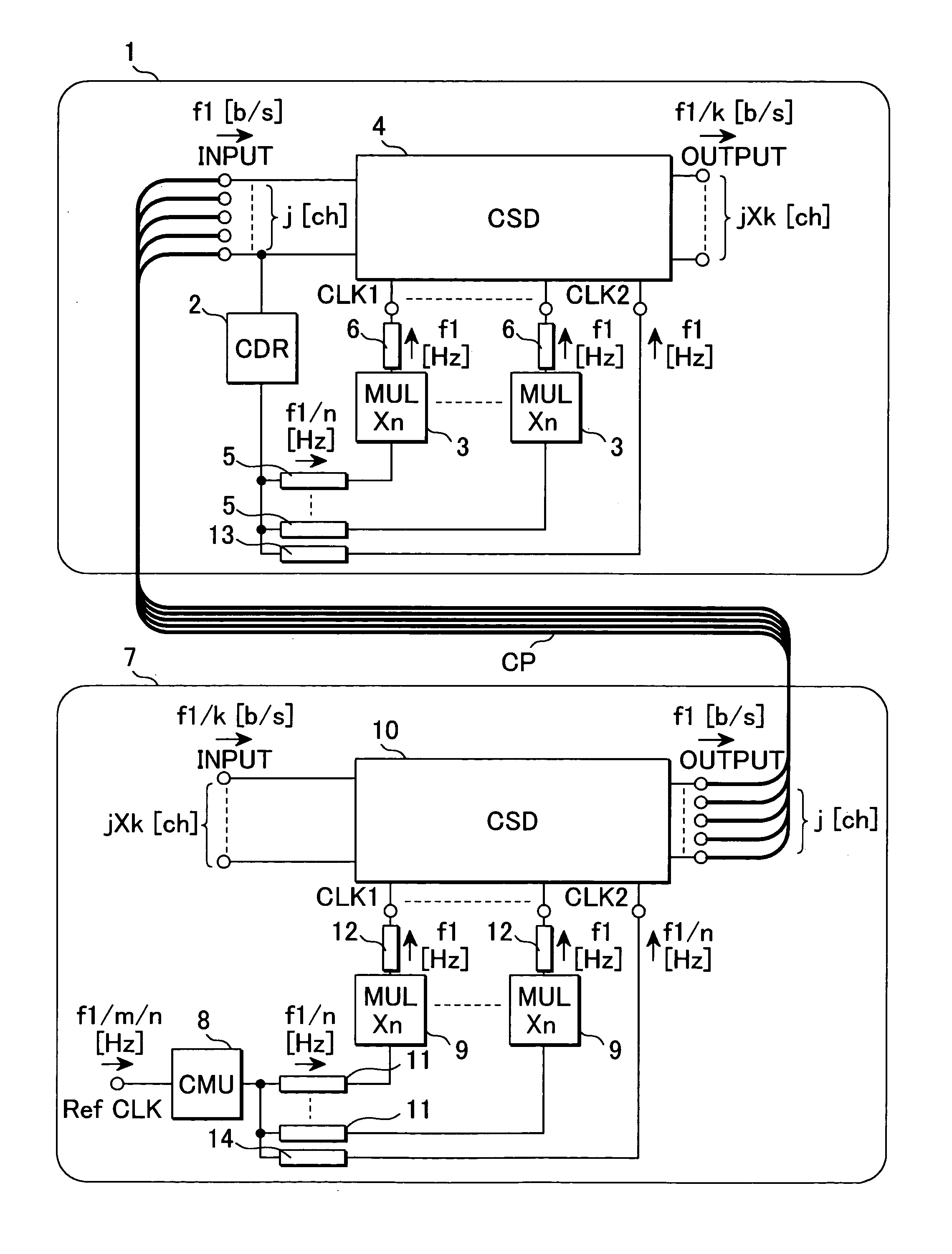
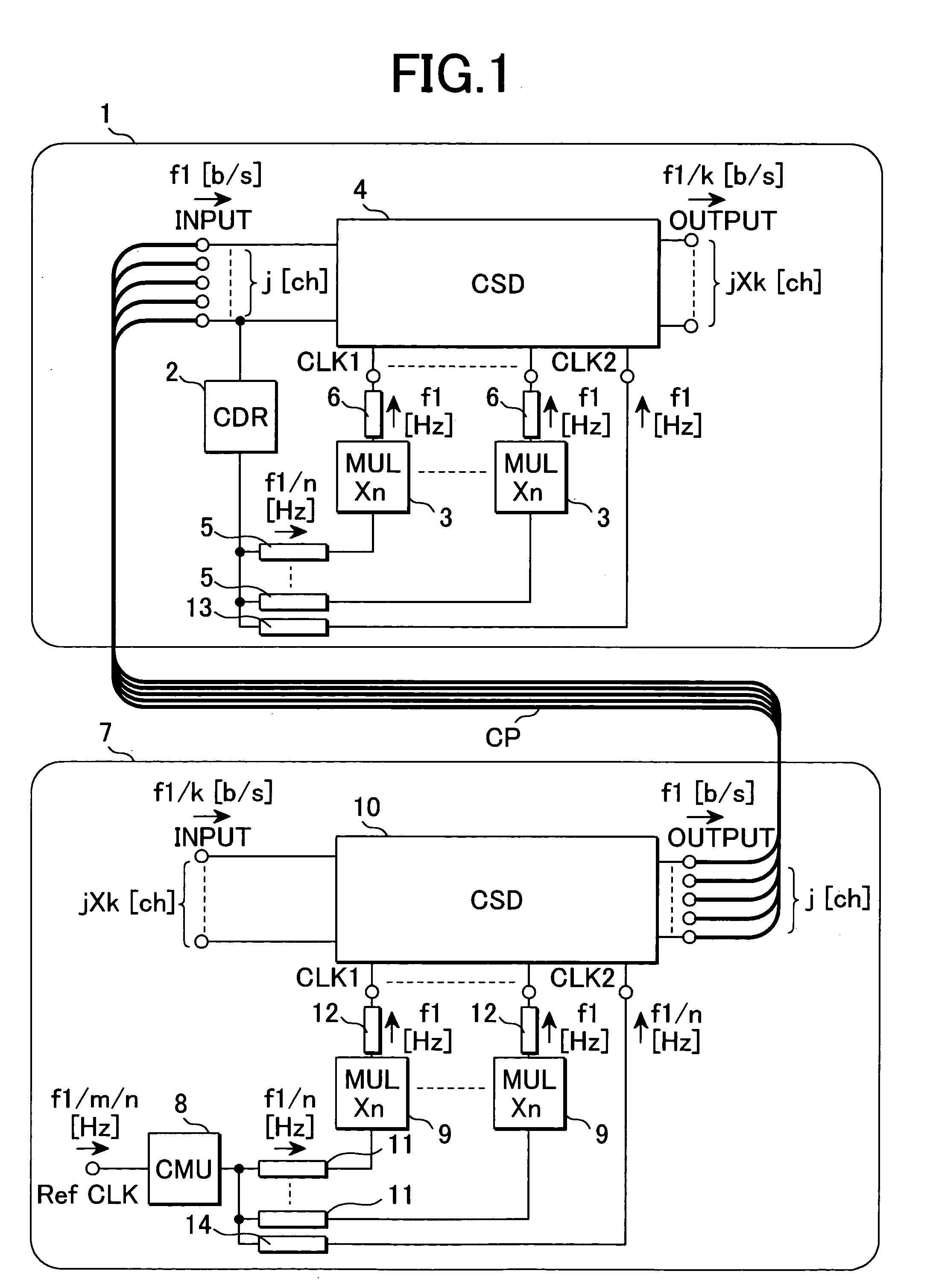
[0045]FIG. 1 is a circuit diagram showing a receiver circuit and a transmitter circuit according to the invention. A receiver circuit 1 shown in FIG. 1 is composed of a synchronous circuit (CDR: clock data recovery) 2 that receives “j” pieces of serial data signals of a data rate of f1 b / s, extracts and recovers a clock signal component having a frequency of f1 / n Hz (n: two or larger natural number) from one data signal of them, a multiplier (MUL) 3 that multiplies the frequency of the clock signal by “n” and a synchronous digital circuit (CSD) 4 that decides and recovers the input data signals using the multiplied clock signal CLK1 as the criterion of timing.
[0046]The output terminal of the synchronous digital circuit 4, that is, the output terminal of the receiver circuit outputs parallel signals of a data rate of f1 / k b / s and “j×k” channels acquired by demultiplexing the input serial data signals.
[0047]Assuming that interconnect 5 that connects the output terminal of the synchron...
second embodiment
[0066]FIG. 5 is a circuit diagram showing the receiver circuit and the transmitter circuit according to the invention.
[0067]A circuit equivalent to this embodiment is a transceiver circuit that performs the time division multiplexing of “k:1” based upon “k” pieces of parallel signals, transmits data the data rate of which is f1 b / s on one transmission line and can demultiplex and recover a time-division multiplexed signal in “1:k” again. In FIG. 5 and the following description, a case of “k=16” is given for an example, however, it need scarcely be said that “k” may be also 2 or a larger natural number.
[0068]In shown in FIG. 5, a receiver circuit (RCV) 1a is composed of a synchronous circuit 2c that receives a serial data signal the data rate of which is f1 b / s, recovers and outputs a clock based upon the data signal, a multiplier 3a, a flip-flop for decision 4a that decides and recovers the data signal, a demultiplexer (DEMUX) 22b that performs the demultiplexing of “1:2” and freque...
third embodiment
[0082]FIG. 6 is a circuit diagram showing the receiver circuit and the transmitter circuit according to the invention.
[0083]This embodiment is different from the first embodiment shown in FIG. 1 in configuration in which a clock signal is distributed. A clock signal having a frequency of f1 / n Hz and output from respective synchronous circuits 2d, 8b in a receiver circuit 1b and a transmitter circuit 7b is respectively branched and is input to multipliers 3b, 9b that output a clock signal having a frequency of “n” times via interconnects 5b, 11b and multipliers 3c, - - - , 9c, - - - that similarly output that output frequencies of n / 2 times, n / 4 times, - - - , f1 / n×2 times.
[0084]Besides, the clock signal is input to each frequency divider 20d that outputs a half frequency, the output is cascaded and frequencies of f1 / n / 2 Hz, f1 / n / 4 Hz, - - - , f1 / k Hz are output. Clock signals respectively output from the multipliers, the frequency dividers and the synchronous circuits are input to r...
PUM
 Abstract
Description
Claims
Application Information