High spectral efficiency, high performance optical MUX and DEMUX architecture

a technology of optical mux and demux, which is applied in the direction of multiplex communication, instruments, optical elements, etc., can solve the problems of reducing the spectral efficiency of the system, requiring small bandwidth of filters, and requiring smaller channel spacing, so as to achieve high spectral efficiency and reduce cost and complexity. , the effect of high spectral efficiency

Inactive Publication Date: 2007-05-22
CIENA
View PDF14 Cites 19 Cited by
  • Summary
  • Abstract
  • Description
  • Claims
  • Application Information

AI Technical Summary

Benefits of technology

[0012]The present invention discloses a high performance optical architecture for multiplexing and demultiplexing channels for use in high spectral efficiency optical systems. In general, the MUX and DeMUX architectures of the present invention w

Problems solved by technology

Such conventional schemes are, therefore, disadvantageous in that multiple filters are required, adding to cost and complexity.
However, there is a penalty in that the filters must have small bandwidths, smaller than the channel spacing because of the requirement to provide isolation and a second transmission path for adjacent channels.
The channel spacing can be increased to mitigate this optical filtering penalty, but the introduction of such ‘dead-bands’ decreases the spectral efficiency of the system making it less cost-effective.
However, the amplitude and phase distortion of these filters

Method used


Image

  • High spectral efficiency, high performance optical MUX and DEMUX architecture
  • High spectral efficiency, high performance optical MUX and DEMUX architecture
  • High spectral efficiency, high performance optical MUX and DEMUX architecture

Examples


second embodiment

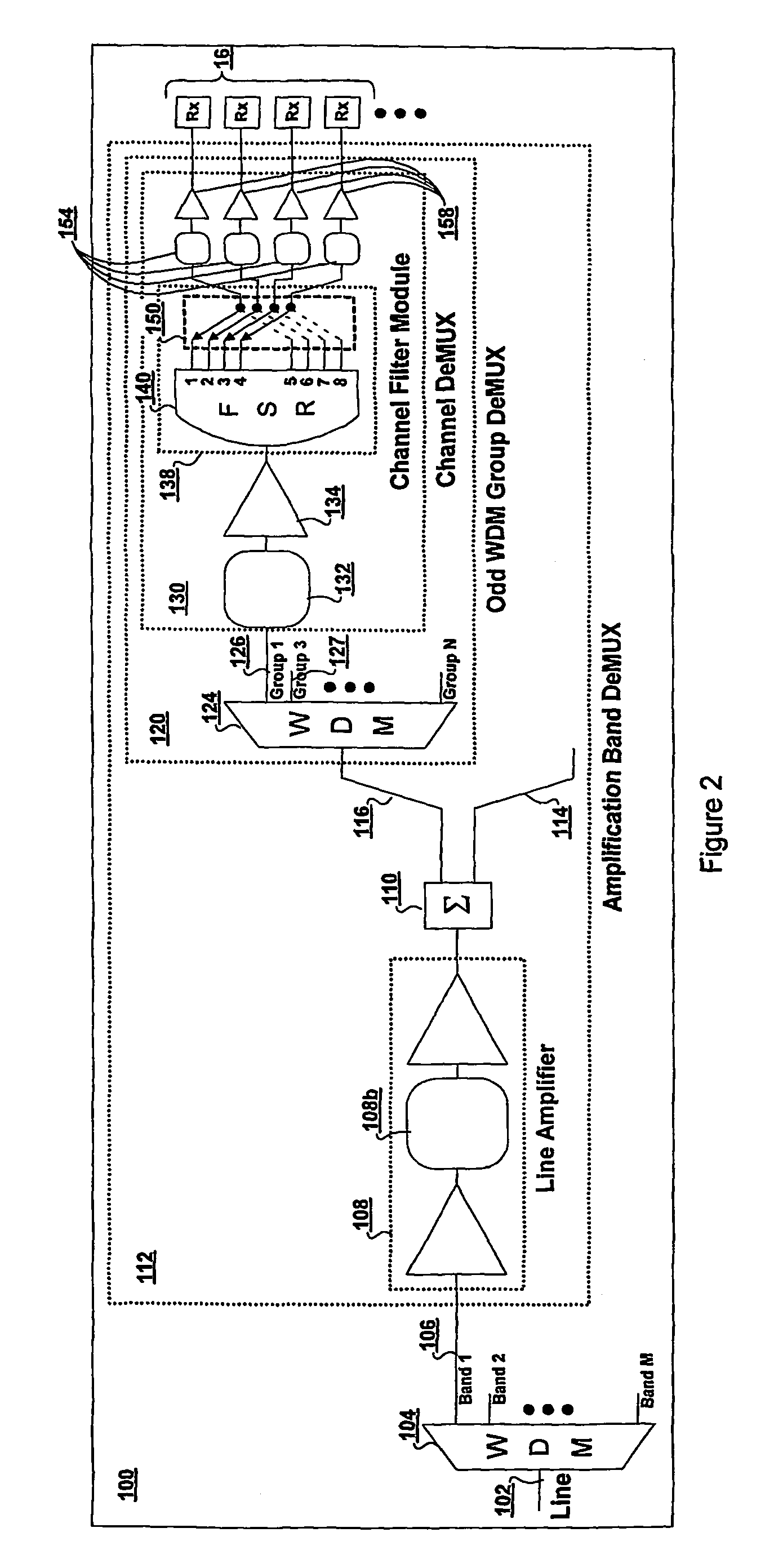
[0040]A motivation underlying the present invention is to provide MUX and DeMUX functions for bands of wavelengths suitable for optical amplification in a fiber optic communication system while maximizing system performance and reach. In this respect, a multiple band system can be realized by replicating the soon-to-be described MUX and DeMUX architecture for each band independently. In general, the MUX and DeMUX architectures of the present invention will fall into two key sections: a wavelength group section and a channel section. In the wavelength group section, groups of multiplexed channels are separated from an from an optical signal having a plurality of multiplexed groups. These groups of multiplexed channels have an associated characteristic for separating said groups. In one embodiment of the invention, this characteristic is characteristic for separating groups comprises alternating groupings of odd or even parity. In a second embodiment, said characteristic for separatin...

first embodiment

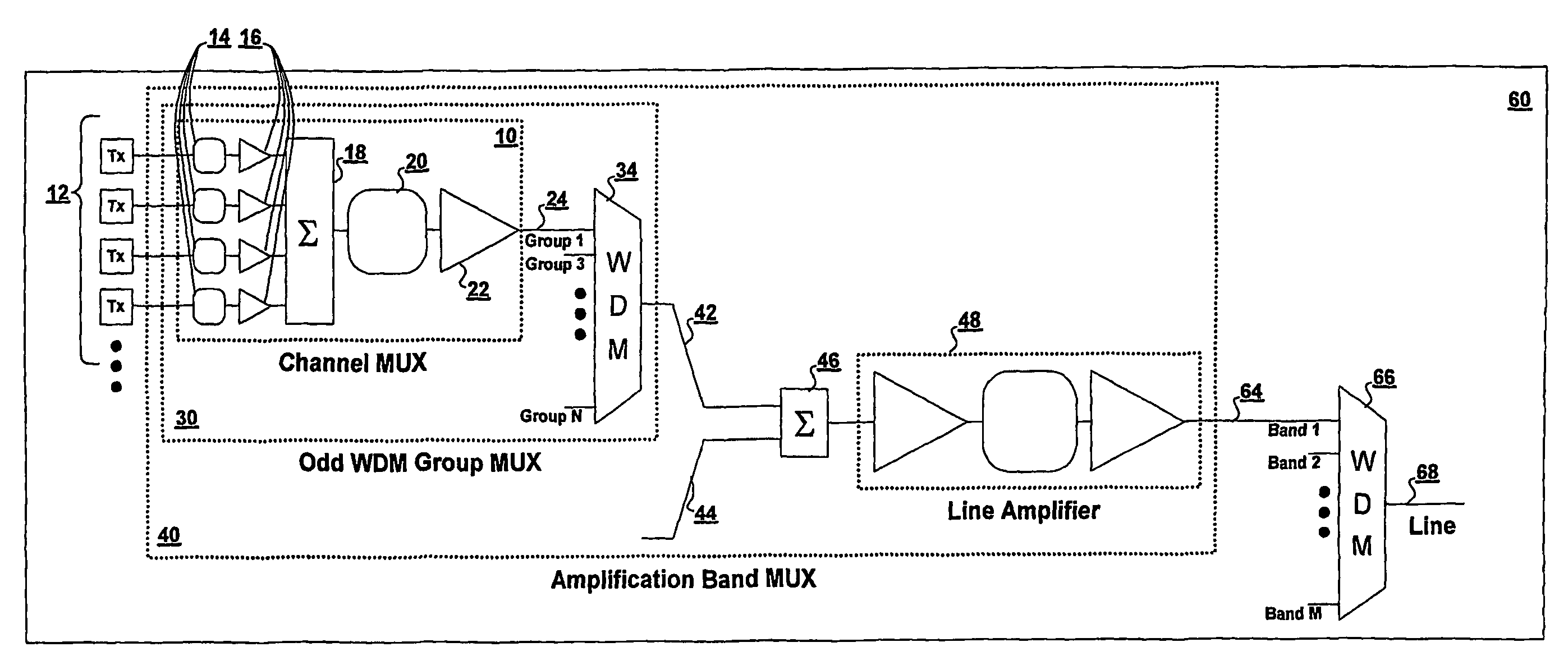
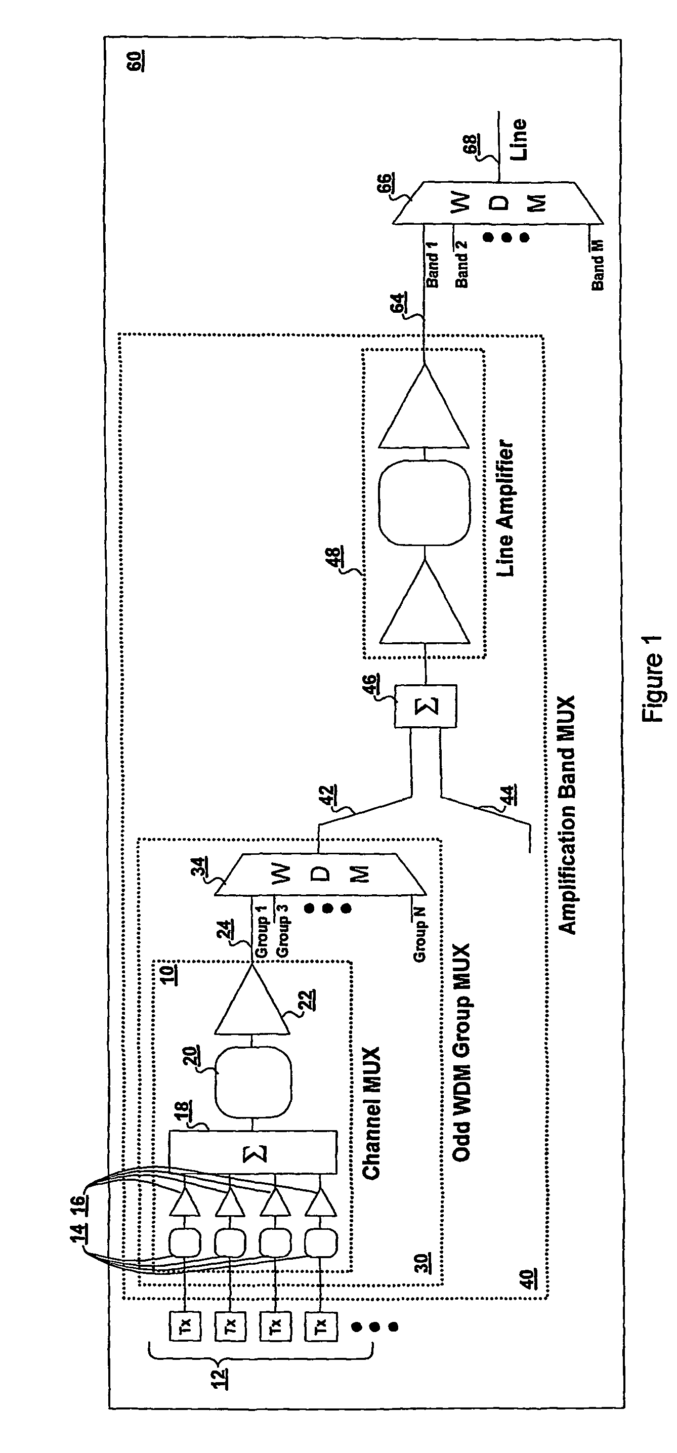
[0041]FIG. 1 is a schematic drawing showing the architecture of an optical multiplexer (MUX) 60 according to the present invention. The multiplexer 60 consists of several stages: a Channel Mux 10, an odd WDM group MUX 30 and an amplification band MUX 40, each stage having been designed with a specific purpose in mind. At the input side, a plurality of transmitters TX is assumed each providing an optical signal on a unique wavelength channel.

[0042]In FIG. 1, a subset of the plurality of transmitters Tx forms a first WDM group 12 (in this case, 4 channels per WDM group) which feeds through a set of dispersion compensation elements 14 and a set of single channel amplifiers 16 and into a passive combiner 18. The output of the combiner 18 is connected to a WDM group dispersion compensation element 20 which then feeds into a WDM group amplifier 22. This arrangement of elements constitutes a first Channel Mux stage 10 of the optical MUX architecture. Generally, in any practical system, the...


PUM


Abstract

The present invention discloses a high performance optical architecture for multiplexing and demultiplexing channels for use in high spectral efficiency optical systems. In general, the MUX and DeMUX architectures of the present invention will fall into two key sections or stages: a wavelength group section and a channel section. The group section makes use of characteristic associated with groups of multiplexed channels for separating said groups from an optical signal having a plurality of multiplexed groups. Advantageously, in preferred embodiments, the channel section is colorless (non-wavelength specific between groups) in order to reduce cost and complexity. With respect to the colorless channel section, components with free spectral ranges (FSRs) have been strategically added to provide repetitive optical filtering functions on group of channels (i.e., subsets of channels within each band of wavelengths) so that the colorless channel section can operate in any respective group identically. Hence each of said colorless channel sections are interchangeable. Advantageously Distortion compensation can be performed on a per group basis.

Description

FIELD OF THE INVENTION[0001]The present invention relates to the field of optical multiplexing and demultiplexing and, more particularly, to a high spectral efficiency, high performance optical multiplexer and demultiplexer architecture.[0002]This application relates to an optical demultiplexing system and method Filed: Apr. 3, 2001 (the same day as the priority application for the present application), by James E. WHITEAWAY, Andrew J. COLLAR, and Stephen DAY, to be assigned to the assignee of the present application.BACKGROUND OF THE INVENTION[0003]Wavelength division multiplexing is a commonly used technique that allows the transport of multiple optical signals on an optical fiber. The ability to carry multiple signals on a single fiber allows that fiber to carry a tremendous amount of traffic, including data, voice, video, etc. By using wavelength division multiplexing it is possible to use a single fiber for multiple channels, as opposed to the costly process of installing addit...

Claims


Application Information

Patent Timeline
IPC IPC(8): G02B6/28G02B6/42H04J14/00H04J14/02H04B10/2513
CPCH04B10/2513H04J14/02H04J14/0208H04J14/0209H04J14/0213H04J14/0212
Inventor BOERTJES, DAVID W.ROBERTS, KIM B.
Owner CIENA
Why Eureka
Try Eureka