

Etching reagent, and method for manufacturing electronic device substrate and electronic device
- Summary
- Abstract
- Description
- Claims
- Application Information
AI Technical Summary
Benefits of technology
Problems solved by technology
Method used
Image

Examples
first embodiment
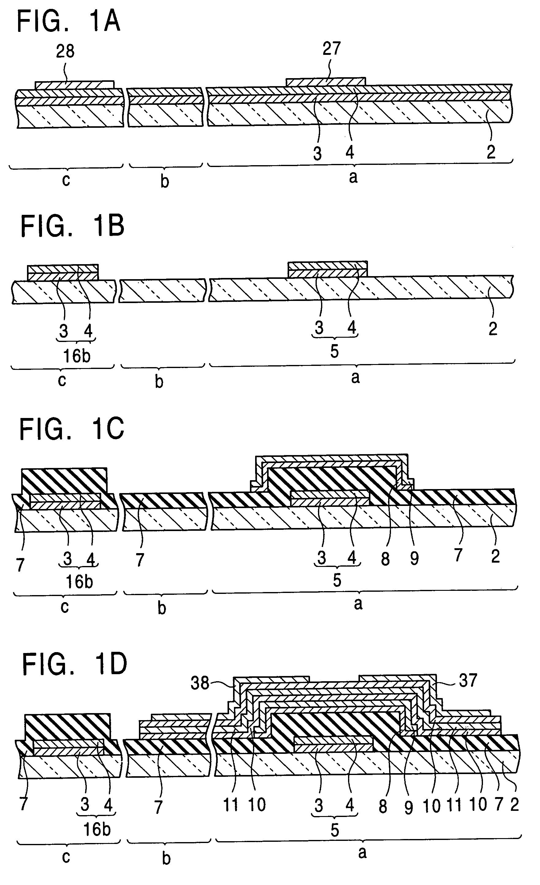
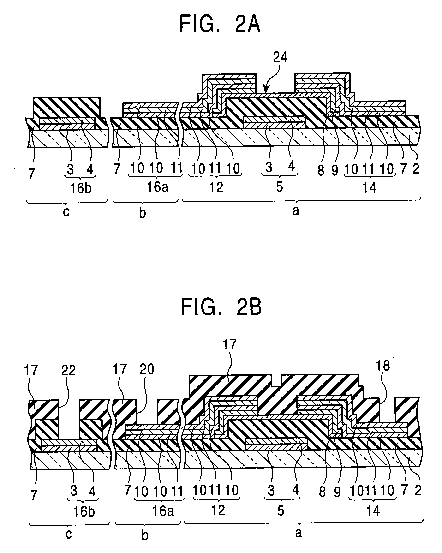
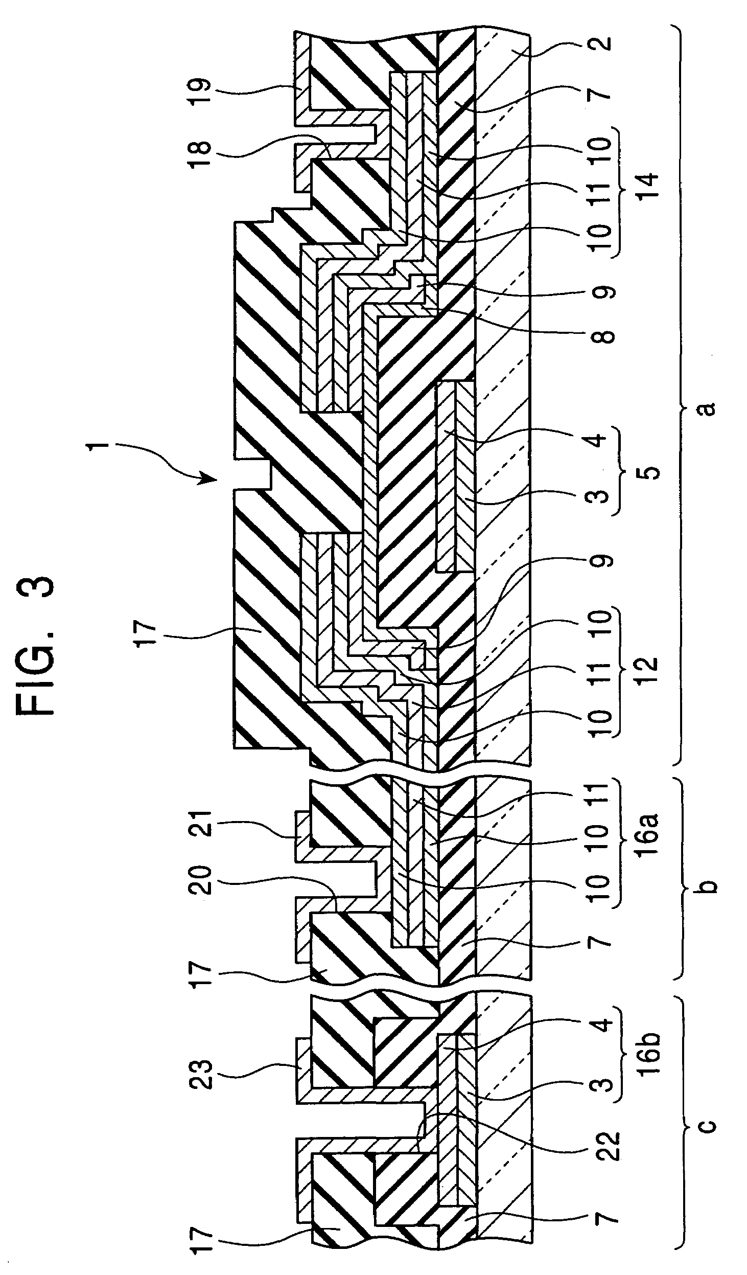
[0061]FIG. 3 is a partial cross section showing an example of the thin film transistor substrate manufactured by applying the method for manufacturing the electronic device substrate according to the present invention to a method for manufacturing a thin film transistor substrate (the method for manufacturing the thin film transistor substrate according to the first embodiment) provided in a liquid crystal display device.
[0062]The portions with reference marks a, b and c denote a thin film transistor portion (TFT), a terminal portion of a source wiring located at outside of a TFT matrix and a terminal portion of a gate wiring, respectively. Although these three portions are located with some distances apart in the actual liquid crystal device provided with this thin film transistor substrate 1, and they can not be naturally exhibited simultaneously in the drawing, they are illustrated as if they are in adjacent relations one another for the convenience of illustration.
[0063]The thin...
second embodiment
[0093]The method for manufacturing the thin film transistor substrate according to the second embodiment of the present invention will be described hereinafter.
[0094]The method for manufacturing the thin film transistor substrate according to the second embodiment differs from the method for manufacturing the thin film transistor substrate according to the first embodiment in that a laminated film of a Mo or Mo alloy film and Cu film is formed for the laminated film for forming the gate electrode 5 and the lower pad layer 16b, and a laminated film provided with the Mo or Mo alloy films on the upper and lower faces of the Cu film is formed for forming the source electrode 12, the drain electrode 14 and the lower pad layer 16a. An aqueous solution containing potassium hydrogen peroxomonosulfate, phosphoric acid and nitric acid is used for the etching agent for these laminated films.
[0095]It is preferable for allowing respective metallic films constituting the laminated film to be etch...
third embodiment
[0097]The method for manufacturing the thin film transistor substrate according to the third embodiment of the present invention will be described hereinafter.
[0098]The method for manufacturing the thin film transistor substrate according to the third embodiment differs from the method for manufacturing the thin film transistor substrate according to the first embodiment in that a laminated film of a Cr or Cr alloy film and the Cu film is formed for the laminated film for forming the gate electrode 5 and the lower pad layer 16b, a laminated film of a Cr or Cr alloy film and the Cu film is formed for the laminated film for forming the source electrode 12, the drain electrode 14 and the lower pad layer 16a. An etching agent comprising an aqueous solution containing hydrogen potassium peroxosulfate and hydrochloric acid is used for etching these laminated films.
[0099]It is preferable for allowing respective metallic films constituting the laminated film to be etched at approximately th...
PUM
| Property | Measurement | Unit |
|---|---|---|
| Fraction | aaaaa | aaaaa |
| Fraction | aaaaa | aaaaa |
| Thickness | aaaaa | aaaaa |
Abstract
Description
Claims
Application Information