
Tunable laser with magnetically coupled filter

Inactive Publication Date: 2007-06-12
INTEL CORP
View PDF152 Cites 19 Cited by
  • Summary
  • Abstract
  • Description
  • Claims
  • Application Information

AI Technical Summary

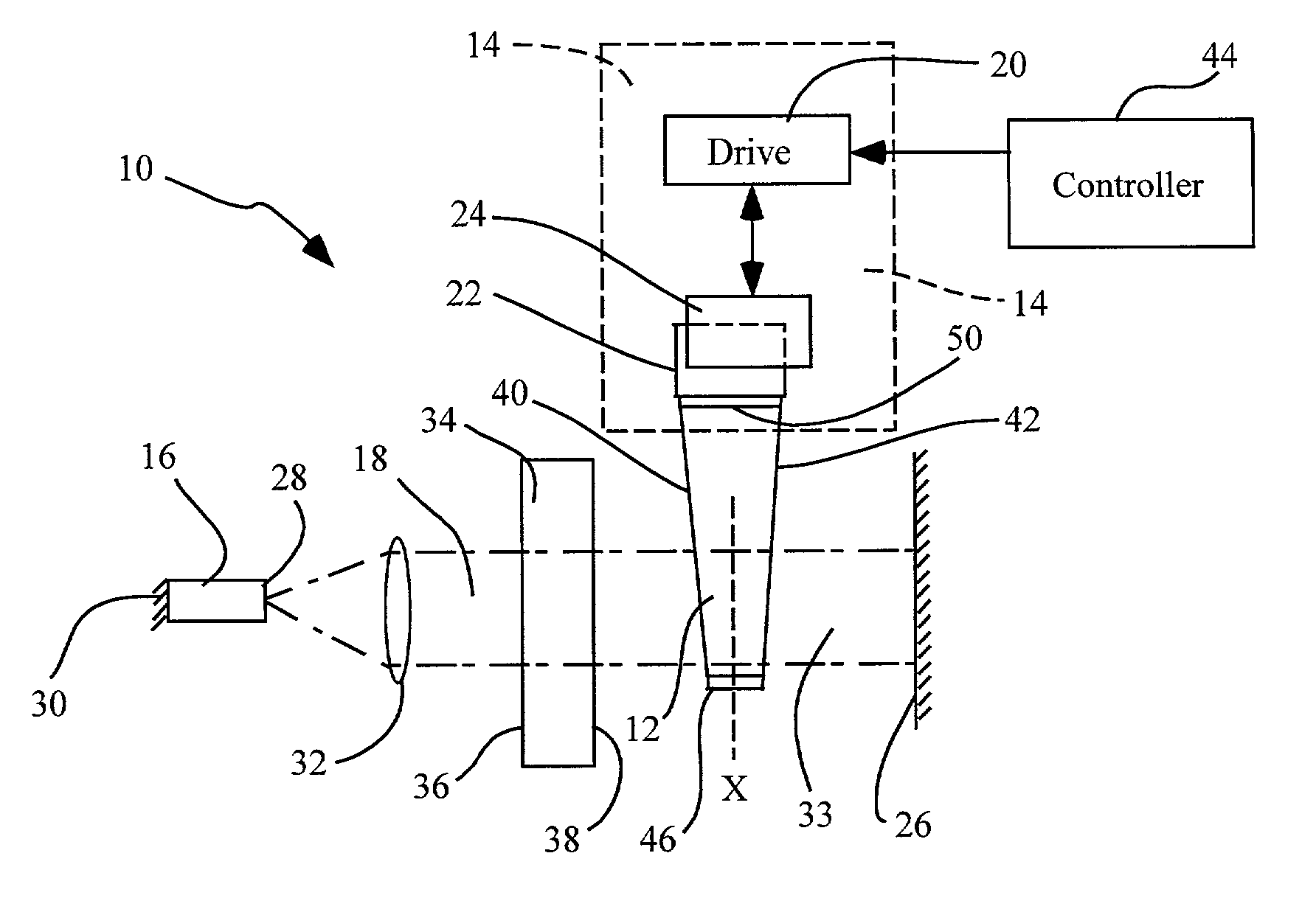
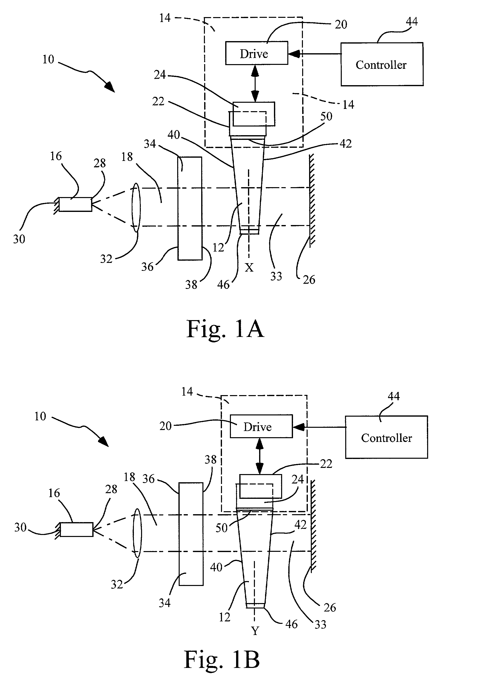
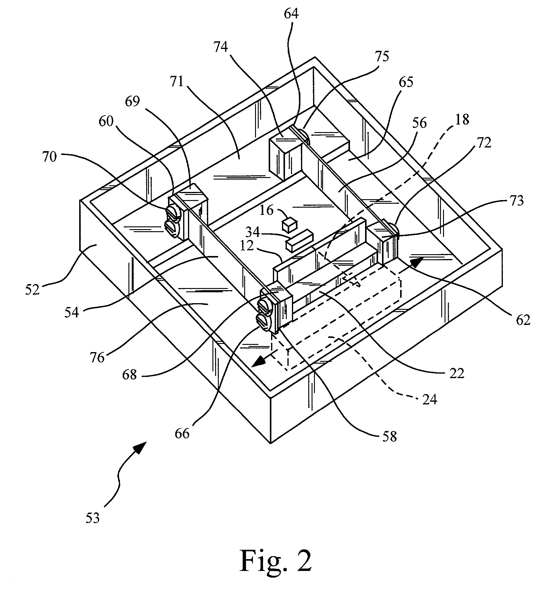
Benefits of technology

[0010]The use of a hermetically sealable container in accordance with the invention permits enclosing an external cavity laser within a contamination-free or low contamination environment, in an inert atmosphere, which protects the anti-reflective (AR) coating on the gain medium, as well as optical surfaces on the end reflector, tuning element and other optical components. The deposition of contaminants onto optical associated with an external cavity laser, which may occur in the absence of hermetic sealing, can result in aberrations which hinder the performance of the external laser cavity and promote degradation of critical optical surfaces.
[0011]The invention provides for magnetically coupling a drive element or assembly that is external to a hermetically sealed container, to a tunable element within the hermetically sealed container, such that the tuning element can be magnetically actuated by the drive assembly while potential contaminants associated with the drive assembly are external to the hermetically sealed container. Many of the components associated with drive assemblies, such as lubricants, adhesives, cable insulators and plasticized parts, can have high outgassing characteristics during laser operation such that volatile hydrocarbons are emitted from the drive assembly. The magnetic coupling of a tuning element within a hermetically sealed enclosure, by a drive assembly located outside of the enclosure, eliminates the risk of laser optical surface contamination by drive assembly components.
[0012]In certain embodiments, one or more activated carbon drains may be included within the hermetically sealed enclosure and positioned to collect volatile hydrocarbons produced by outgassing from components of the external cavity laser. The activated carbon drain has a large surface area of activated carbon that allows for adsorbing or trapping the outgassing volatile organic compounds that occur during the operation of the laser. Organic hydrocarbon materials released from epoxies and lubricants used during the assembly of the external cavity laser or utilized in sealing the hermetically sealable enclosure are also trapped by the activated carbon drain. The activated carbon drain allows the optical surfaces of the tunable external cavity laser to remain free of organic contaminants in the hermetically sealed enclosure that would otherwise hinder performance.
[0013]In other embodiments, one or more moisture traps may be included within the hermetically sealable container and positioned to collect water vapor that may outgas from polyimide or other moisture holding insulator or material present in the external cavity laser. Such outgassed water vapor, if not trapped, may condense on critical optical surfaces and reduce performance of the external cavity laser, and may promote corrosion of components. Moisture condensation is particularly a concern after “cooldown” periods when the laser has not been in use. The material of the moisture trap may comprise a variety of desiccants. The moisture trap prevents condensation of water on optical surfaces and elsewhere that would otherwise reduce performance in the operation of the external cavity laser and promote corrosion of laser components within the hermetically sealed enclosure.
[0016]In certain embodiments, selective heating of important optical surfaces may be employed to prevent condensation of contaminants thereon. Such heating may be employed during cool-down periods when the gain medium is not powered, to prevent condensation when the external cavity laser is not in use. One or more heat sources, either positioned internally or externally to the hermetically sealed enclosure, may be used to heat the gain medium of the external cavity laser when the gain medium is not powered, in order to maintain a relatively high temperature for the anti-reflective coating on the output facet of the gain medium to prevent condensation thereon when the laser is not in use. Heating in this manner may also be used in connection with the end mirror, tunable elements or other components with sensitive optical surfaces to maintain a temperature higher than the activated carbon drain, moisture trap and / or the sacrificial surface present in the hermetically sealed container, to further prevent the contamination of these optical surfaces.

Problems solved by technology

Greater bandwidth requirements will likely result in smaller channel separation in the future.
The advent of continuously tunable telecommunication lasers has introduced additional complexity to telecommunication transmission systems, as individual lasers must be able to provide stable, accurate tuning at narrowly separated channel wavelengths.
Further, external cavity laser tuning typically involves drive elements that can introduce contaminants to the laser optical surfaces.
These deficiencies have resulted in increased costs and decreased performance lifetimes for tunable telecommunication transmitter lasers.

Method used


Image

  • Tunable laser with magnetically coupled filter
  • Tunable laser with magnetically coupled filter
  • Tunable laser with magnetically coupled filter

Examples


Embodiment Construction

[0023]Referring more specifically to the drawings, for illustrative purposes the present invention is embodied in the apparatus and method shown in FIG. 1 through FIG. 5. It will be appreciated that the apparatus may vary as to configuration and as to details of the parts, and that the method may vary as to details and the order of the acts, without departing from the basic concepts as disclosed herein. The invention is disclosed primarily in terms of an external cavity diode laser (ECDL) used as a telecommunication transmitter laser. However, it will be readily apparent to those skilled in the art that the invention may be used with a variety of other laser devices and optical systems. It also should be understood that the terminology used herein is for the purpose of describing particular embodiments only, and is not intended to be limiting.

[0024]Referring now to FIGS. 1A and 1B, there is shown a laser apparatus 10 comprising a tuning element 12, and a drive assembly 14 that is ma...


PUM


Abstract

Laser apparatus and methods that permit actuation of a tuning element via a magnetically coupled drive assembly, and which provide for isolation of contamination-sensitive optical surfaces within a hermetically sealed enclosure with a magnetically coupled drive assembly that is external to the enclosure. The apparatus of the invention comprises a tuning element positioned in a light beam, and a drive element magnetically coupled to the tuning element. The apparatus may further comprise a hermetically sealed enclosure, with the tuning element positioned within the hermetically sealed enclosure, and the drive element located outside the hermetically sealed enclosure. The methods comprise positioning a tuning element in a light beam, magnetically coupling a drive element to the tuning element; and actuating the tuning element via magnetic coupling between the tuning element and the drive element. The methods may further comprise enclosing the tuning element in a hermetically sealed container.

Description

BACKGROUND OF THE INVENTION[0001]The demand for increased bandwidth in fiberoptic telecommunications has driven the development of sophisticated transmitter lasers usable for dense wavelength division multiplexing (DWDM) systems wherein multiple separate data streams propagate concurrently in a single optical fiber. Each data stream is created by the modulated output of a semiconductor laser at a specific channel frequency or wavelength, and the multiple modulated outputs are combined onto the single fiber. The International Telecommunications Union (ITU) presently requires channel separations of approximately 0.4 nanometers, or about 50 GHz, which allows up to 128 channels to be carried by a single fiber within the bandwidth range of currently available fibers and fiber amplifiers. Greater bandwidth requirements will likely result in smaller channel separation in the future.[0002]DWDM systems have largely been based on distributed feedback (DFB) lasers operating with a reference et...

Claims


Application Information

Patent Timeline
IPC IPC(8): H01S3/10H01S3/08H01S3/106H01S3/16H01S5/022H01S5/14
CPCH01S5/141H01S3/1062H01S3/1681H01S5/02216H01S5/0222H01S5/02248H01S5/02284H01S5/142H01S5/02325H01S5/02251
Inventor JOHNSON, BRAD V.
Owner INTEL CORP
Learn More