Methods and apparatus for imaging using a light guide bundle and spatial light modulator

a technology of spatial light modulator and light guide bundle, which is applied in the field of imaging using light guide bundles, can solve the problems of reducing resolution, cumbersome confocal microscopes, and increasing imaging speed, so as to reduce cross-talk, enhance sensitivity, contrast or resolution of images, and reduce the amount of noise or stray light

Inactive Publication Date: 2007-06-26
MOTIC CHINA GRP CO LTD
View PDF22 Cites 44 Cited by
  • Summary
  • Abstract
  • Description
  • Claims
  • Application Information

AI Technical Summary

Benefits of technology

[0009]The present invention comprises microscopes and methods that have significant advantages in controlling the light that contacts a sample and/or that is detected emanating from a sample. The microscopes and methods, which preferably relate to confocal microscopes and further preferably confocal endoscopes for in vivo imaging, comprise a spatial light modulator in the illumination and/or detection light path so that light transmitted to the target, for example via a bundle of light guides, is transmitted substantially only into the cores of the lig...

Problems solved by technology

Other confocal scanning systems have used a laser beam rastered with rotating mirrors to scan a specimen or a laser beam that scans a slit rather than a spot; such slit scanning increases imaging speed but slightly degrades resolution.
Confocal microscopes typically use a bulky design in which several large components—including a laser system as the light source, detection pinholes, ...

Method used


Image

  • Methods and apparatus for imaging using a light guide bundle and spatial light modulator
  • Methods and apparatus for imaging using a light guide bundle and spatial light modulator
  • Methods and apparatus for imaging using a light guide bundle and spatial light modulator

Examples


example

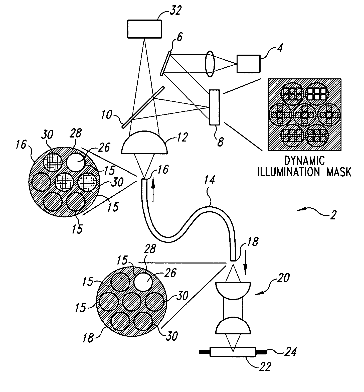
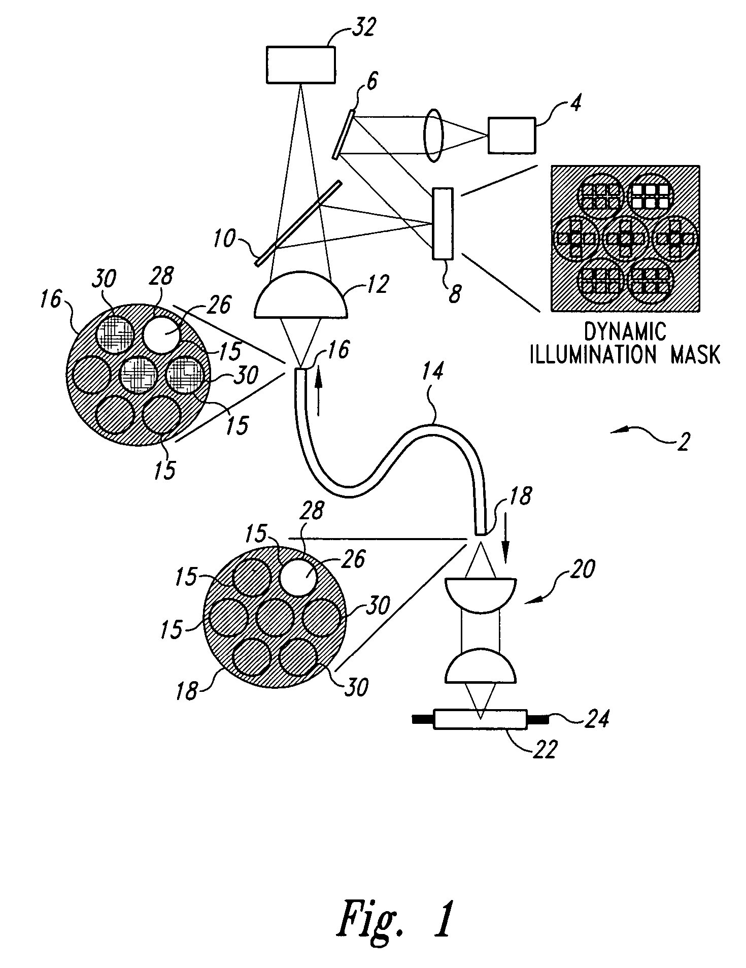
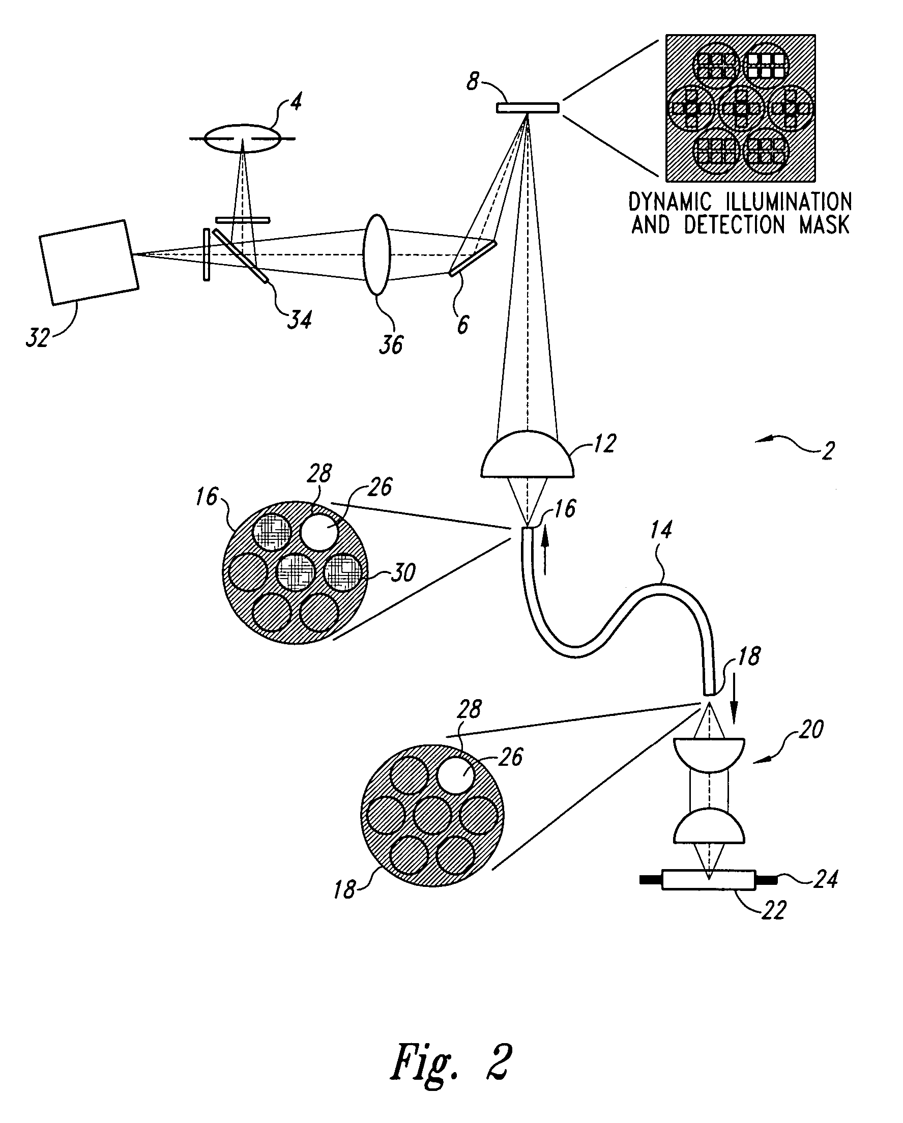
[0108]A system according to FIG. 1 was constructed to demonstrate confocal imaging through a fiber bundle. A digital micromirror device (DMD) from Texas Instruments (Dallas, Tex.) was employed as the SLM because of its high contrast high pixel count, and fast temporal response. The DMD micromirrors had a center-to-center spacing of 17 μm and a mechanical switching time of 15 μs. L. J. Hombeck, Proc. SPIE 3013, 27 (1997). A 640×480 resolution DMD with a full on-off contrast ratio of 255:1 was employed in this work; higher resolution (1280×1024) and increased contrast (370:1) devices are now available.

[0109]A Sumitomo IGN-08 / 30 image guide (30,000 fibers, 2 μm fiber diameter, 3 μm center-to-center spacing, 0.35 NA) was positioned in the object plane of a conventional microscope configured for reflected light epi-illumination. The DMD was positioned in the illumination path of the microscope such that it was conjugate to the object plane. The contrast of the DMD was maximized because t...


PUM


Abstract

Endoscopes and other viewing devices that control the light that contacts a sample and/or that is detected emanating from a sample. The viewing devices are particularly well suited for in vivo imaging, although other uses are also included. The viewing devices, and methods related thereto, comprise a spatial light modulator in the illumination and/or detection light path so that light transmitted to the target via a bundle of light guides or optical system is transmitted substantially only into the cores of the light guide bundle and not into the cladding surrounding the light guides, filler between the light guides in the bundle, or undesired light guides. Also, methods and apparatus for mapping the pixels of the spatial light modulator to the cores of the light guides in the bundle (preferably at least 3 pixels (e.g., at least 3 mirrors for a digital micromirror device) for each core), as well as for mapping the light guides of one light guide bundle to another.

Description

CROSS-REFERENCE TO RELATED APPLICATIONS[0001]The present application is a divisional patent application of U.S. patent application Ser. No. 09 / 738,257, filed Dec. 14, 2000, now U.S. Pat. No. 6,663,560, issued Dec. 16, 2003, which application claims priority from U.S. provisional patent application No. 60 / 172,436, filed Dec. 17, 1999, from U.S. provisional patent application No. 60 / 192,081, filed Mar. 24, 2000, and from U.S. provisional patent application No. 60 / 244,427, filed Oct. 30, 2000, all of which are presently pending.FIELD OF THE INVENTION[0002]The field of the present invention is imaging using a light guide bundle.BACKGROUND OF THE INVENTION[0003]Microscopes magnify objects or samples, which can be stationary and moving. One type of microscope is a confocal microscope, which uses a very small spot, or pinhole, of light to make its image of the target. Typically, the spot is scanned across the target in a pointwise, digital fashion and the image is made by combining the poi...

Claims


Application Information

Patent Timeline
IPC IPC(8): A61B1/07G02B26/08G02B6/43G02B21/00G02B23/24G02B23/26
CPCG02B21/0028G02B21/0032G02B21/0056G02B21/0072G02B23/2453G02B23/26A61B1/00165A61B1/00172A61B1/07G02B6/06
Inventor MACAULAY, CALUM E.DLUGAN, ANDREW L. P.LANE, PIERRE M.
Owner MOTIC CHINA GRP CO LTD
Why Eureka
Try Eureka