System and apparatus for measuring displacements in electro-active materials

a technology of electro-active materials and displacements, applied in the direction of liquid/fluent solid measurement, instruments, fluid means, etc., can solve the problems of difficult data interpretation, difficult to precisely attach strain gauges to samples, and easy mechanical cracking and electrical breakdown of samples, etc., to achieve high hydraulic pressure

Inactive Publication Date: 2007-06-26
THE US SEC OFTHE NAVY
View PDF17 Cites 6 Cited by
  • Summary
  • Abstract
  • Description
  • Claims
  • Application Information

AI Technical Summary

Benefits of technology

[0014]Still another object is to provide a means for measuring displacement in electro-active material that will ensure reproducibility of the measurements from sample to sample.

Problems solved by technology

Attempts to measure the electromechanical properties of stack elements often result in data that is difficult to interpret since the epoxy adhesive, metal electrodes and compression fixture tend to mask the properties of the ceramic.
The required geometry and small sample size often cause problems with mechanical alignment, and under compressive load, samples are prone to mechanical cracking and electrical breakdown.
Precise attachment of the strain gauges to the samples is difficult, affecting the reproducibility of the measurements from sample to sample.
In addition, temperature gradients within the chamber also affect the ability to repeat the measurements.
For the most part, the prior art apparatus lacks the reliability and precision that is necessary to characterize electro-active ceramics in a reproducible and efficient manner.

Method used


Image

  • System and apparatus for measuring displacements in electro-active materials
  • System and apparatus for measuring displacements in electro-active materials
  • System and apparatus for measuring displacements in electro-active materials

Examples


Embodiment Construction

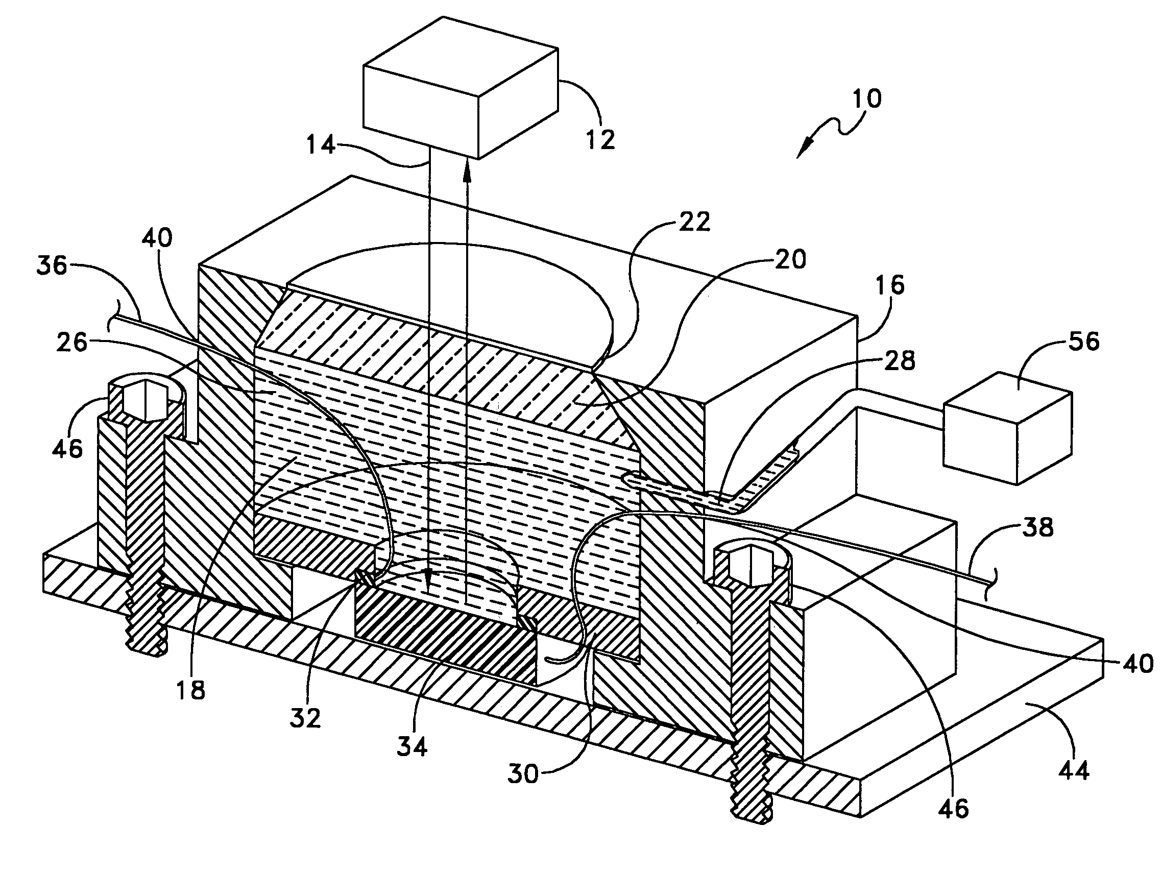
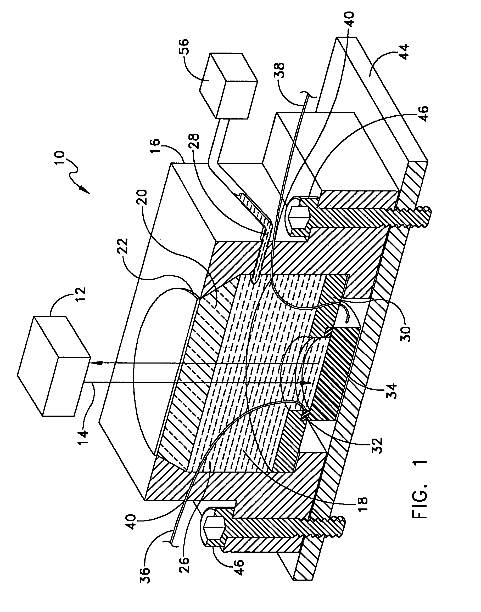
[0019]Referring now to FIG. 1 there is shown a high pressure optical cell 10 in use with a laser interferometer 12. Laser interferometer 12 is configured for a single beam 14. In the preferred embodiment, the cell 10 consists of a stainless steel cell body 16, however, it is to be understood that the present device is not limited to that particular metal and could be made of titanium or other materials. The cell 10 houses a cavity 18 with a single quartz glass window 20 that is transparent to laser radiation of a particular wavelength. In the preferred embodiment, the wavelength is λ=632 nm, but is not limited as such. It is to be understood that the present device is not limited to the use of quartz glass for the window 20 and could be made of other optically transparent materials, providing said materials are transparent to the laser radiation in use. The window 20 has an anti-reflective coating 22 on its surface transparent to light of the same wavelength as the laser beam 14 to ...


PUM

PropertyMeasurementUnit
thicknessaaaaaaaaaa
frequencyaaaaaaaaaa
displacementsaaaaaaaaaa

Abstract

A device designed to apply uniaxial pressure to the surface of an electro-active material while simultaneously applying a current to the material under controlled temperature conditions and then measuring the displacement of the material by means of a laser interferometer. The device involves a housing with a chamber in which a sample of material is secured. The chamber has an aperture with a quartz window that allows the laser beam from the interferometer to pass. The sample is connected to electrodes and the chamber is filled with dielectric oil that applies the uniaxial pressure to one side of the sample. The device is placed onto a thermal control system. When the appropriate thermal and pressure conditions are established, current is applied to the sample and the interferometer measures the displacement.

Description

STATEMENT OF GOVERNMENT INTEREST[0001]The invention described herein may be manufactured and used by or for the Government of the United States of America for governmental purposes without the payment of any royalties thereon or therefore.CROSS REFERENCE TO OTHER RELATED APPLICATIONS[0002]This patent application is co-pending with a related patent application Ser. No. 10 / 914,777 entitled AN IMPROVED SYSTEM AND APPARATUS FOR MEASURING DISPLACEMENTS IN ELECTRO-ACTIVE MATERIALS, by Louis G. Carreiro and Lawrence J. Reinhart both of whom are inventors as to this application.BACKGROUND OF THE INVENTION[0003](1) Field of the Invention[0004]The present invention relates to a device for measuring displacements in a solid material, and more specifically to a device for applying uniaxial hydraulic pressure to the surface of an electro-active material while at the same time permitting a light source to be focused on the same surface in order to perform interferometric non-contact displacement ...

Claims


Application Information

Patent Timeline
Patent Type & Authority Patents(United States)
IPC IPC(8): G01B11/02G01B13/08G01B7/16G01N33/00
CPCG01B11/161G01N33/388
Inventor CARREIRO, LOUIS G.REINHART, LAWRENCE J.
Owner THE US SEC OFTHE NAVY
Why Eureka
Try Eureka