Chemical imaging fiberscope

a fiberscope and fiberscope technology, applied in the direction of optical radiation measurement, diagnostics using spectroscopy, instruments, etc., to achieve the effect of being immune to humidity and temperature changes

Active Publication Date: 2007-07-03
CHEMIMAGE
View PDF15 Cites 25 Cited by
  • Summary
  • Abstract
  • Description
  • Claims
  • Application Information

AI Technical Summary

Benefits of technology

[0011]To address the need for remote chemical inspection technology, a novel flexible fiberscope device has been developed that is Raman chemical imaging capable. The design of the Raman chemical imaging fiberscop...

Problems solved by technology

Second, the Raman chemical imaging fiberscope ...

Method used


Image

  • Chemical imaging fiberscope
  • Chemical imaging fiberscope
  • Chemical imaging fiberscope

Examples


Embodiment Construction

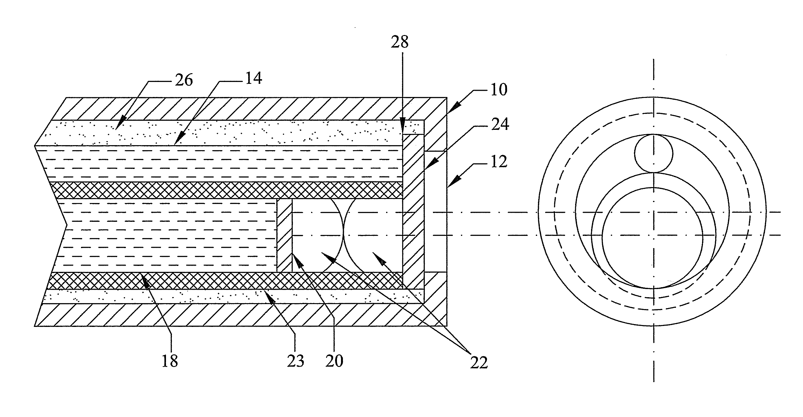
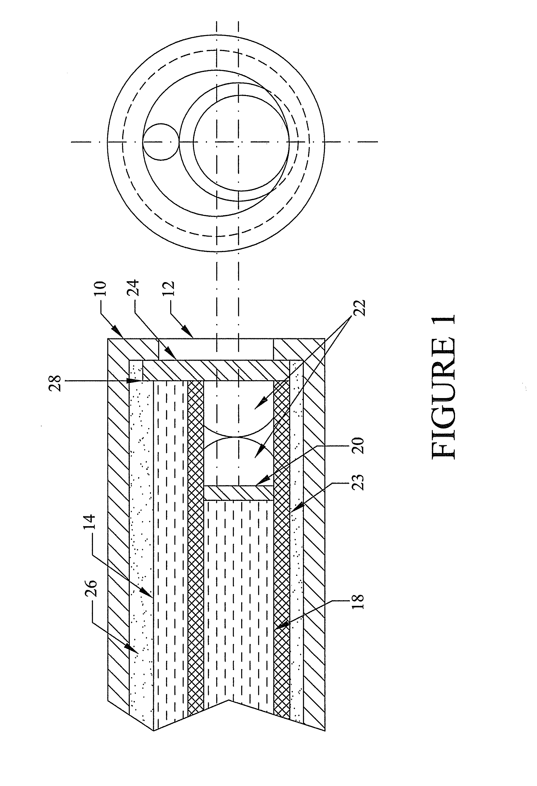
[0024]The Raman chemical imaging fiberscope combines in a single platform a laser beam delivery system to irradiate samples for Raman spectroscopy, an incoherent fiber optic bundle to deliver white light illumination and a coherent fiber bundle suitable for Raman spectral collection, Raman image collection and digital video collection.

[0025]The distal end of the fiberscope is shown in cross-section in FIG. 1. The external housing 10 surrounds the inner core of the fiberscope. The outer jacket is mechanically rugged and immune to hostile sampling environments. At the distal end of the fiberscope is window 12. This window is, in the preferred embodiment, composed of quartz, diamond or sapphire and is used as an optically transparent boundary separating the sample environment from the optical components in the probe.

[0026]Laser illumination fiber 14 delivers laser illumination to the sample. This light passes through laser bandpass filter 24, which filters out all wavelengths of light ...


PUM


Abstract

A fiberscope device is disclosed which is suitable for video imaging, laser Raman spectroscopy and laser Raman spectroscopic (i.e. chemical) imaging. The fiberscope design minimizes fiber background interference arising from the laser delivery fiber optic and the coherent fiber optic light gathering bundle while maintaining high light throughput efficiency through the use of integrated spectral filters. In the fiberscope design, the laser delivery fiber optic is offset from the coherent fiber optic light gathering bundle. The laser delivery field is captured entirely by the light gathering field of view of the coherent fiber bundle. The fiberscope incorporates spectral filter optical elements that provide environmental insensitivity, particularly to temperature and moisture. The fiberscope is suited to the analysis of a wide range of condensed phase materials (solids and liquids), including the analysis of biological materials such as breast tissue lesions and arterial plaques, in such a manner to delineate abnormal from normal tissues.

Description

[0001]This application claims the benefit of U.S. Provisional Application No. 60 / 144,518, entitled “Chemical Imaging Fiberscope” filed Jul. 19, 1999.FIELD OF THE INVENTION[0002]The present invention is related to fiberscope probes for spectroscopic and image analysis, and, in particular, to probes useful for both Raman spectroscopy and Raman chemical imaging.BACKGROUND OF THE INVENTION[0003]Raman chemical imaging combines Raman spectroscopy and digital imaging for the molecular-specific analysis of materials. Raman chemical imaging has traditionally been performed in laboratory settings using research-grade light microscope technology as the image gathering platform. However, Raman chemical imaging is applicable to in situ industrial process monitoring and in vivo clinical analysis. The application of chemical imaging outside the research laboratory has been limited by the lack of availability of stable imaging platforms that are compatible with the physical demands of industrial pr...

Claims


Application Information

Patent Timeline
IPC IPC(8): G02B6/06A61B1/06G01J3/44
CPCA61B1/00165A61B1/0638A61B1/0646A61B1/07A61B5/0075A61B5/0084G01J3/02G01J3/0208G01J3/0218G01J3/0227G01J3/024G01J3/0256G01J3/0262G01J3/0286G01J3/44G02B6/06A61B1/063A61B1/043G01J2003/1213
Inventor TREADO, PATRICK J.NELSON, MATTHEW P.KEITZER, SCOTT A.SMITH, RYAN D.
Owner CHEMIMAGE
Why Eureka
Try Eureka