
Hybrid ship propulsion system

a propulsion system and hybrid technology, applied in the direction of marine propulsion, propulsive elements, vessel construction, etc., can solve the problems of large swept volume, large physical volume with a large mass, large amount of unused dead space,

Inactive Publication Date: 2007-07-10
SIEMENS AG
View PDF11 Cites 30 Cited by
  • Summary
  • Abstract
  • Description
  • Claims
  • Application Information

AI Technical Summary

Benefits of technology

"The invention is a ship propulsion system that is more economical and efficient than existing systems. It uses a combination of an electrical drive and a diesel drive for the ship propeller, with the electric motor providing a significant portion of the torque. This results in lower fuel consumption, increased available useful area, and lower investment costs. The electric motor replaces one or more cylinders of the slow-running diesel engine, making it lighter and easier to accommodate in the ship's hull. The reduced space requirement for the main diesel engine allows for increased cargo capacity without changing the ship's dimensions. The mixed propulsion system with the relatively high electrical propulsion power, in conjunction with the variable-pitch propeller, also allows for regulated fuel consumption and improved life and reduced maintenance work for the main diesel engine. The new propulsion system concept can be easily converted to existing seagoing or cargo ships, without needing to enlarge the engine room. It also allows for higher cruise speeds and increased cargo volume without major changes in the area of the engine room or the main diesel engine."

Problems solved by technology

The high power that is required and the low rated rotation speed result in a large swept volume, and thus a large physical volume with a large mass.
There is also a large amount of unused dead space.
At lower rotation speeds, the fuel consumption can be even worse.
Nevertheless, the optimum operating point cannot be achieved in all movement conditions.
In addition to the poor fuel consumption at rotation speeds below the rated rotation speed, considerable thermal loads also occur at low rotation speeds, such as those which are required in the lower speed of motion range when the ship is being accelerated.
The considerable advantages of an electrical propulsion system are countered by comparatively high investment costs, which are considerably greater than the costs involved for a diesel engine that drives the ship propeller directly.

Method used


Image

  • Hybrid ship propulsion system
  • Hybrid ship propulsion system
  • Hybrid ship propulsion system

Examples


Embodiment Construction

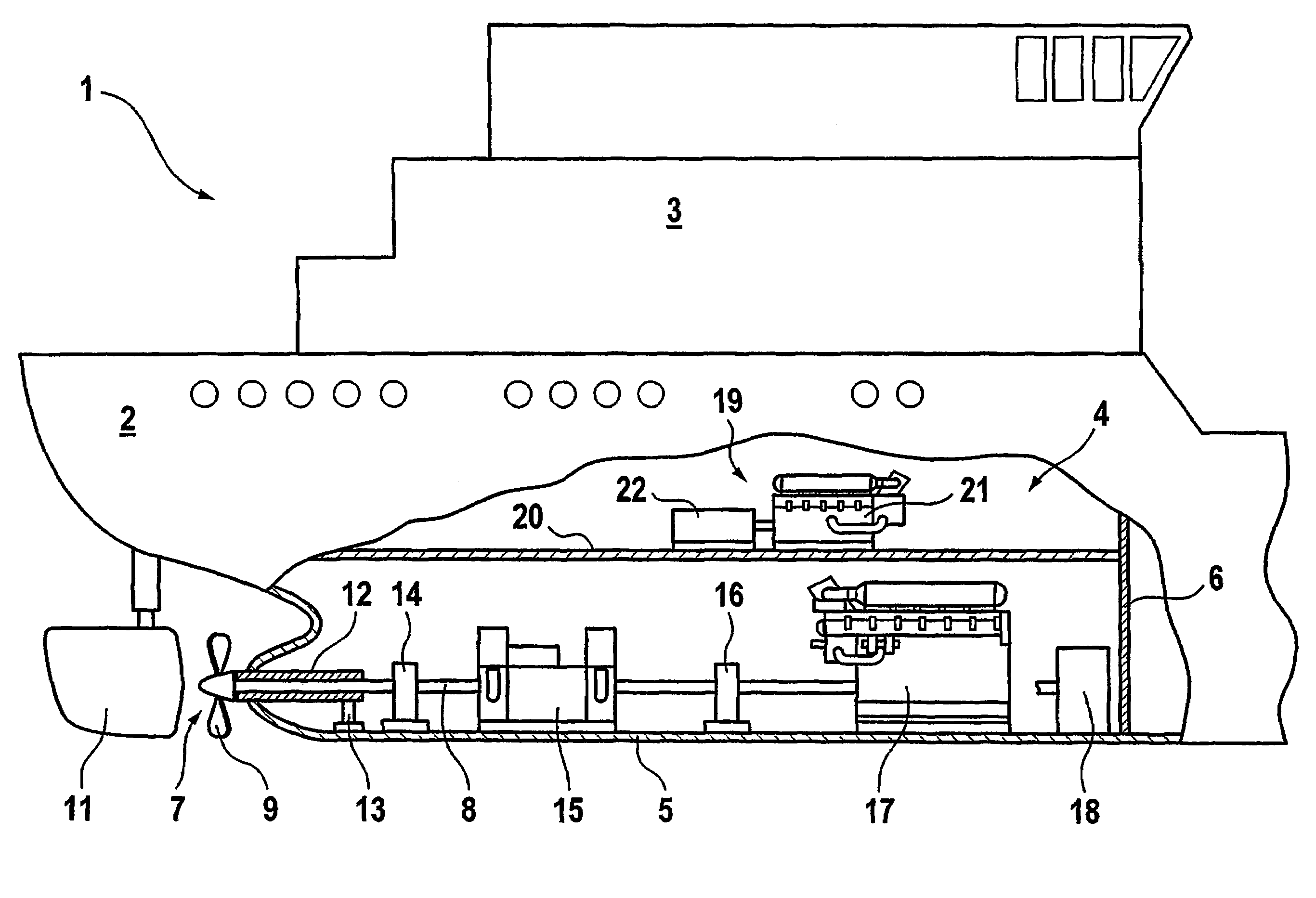
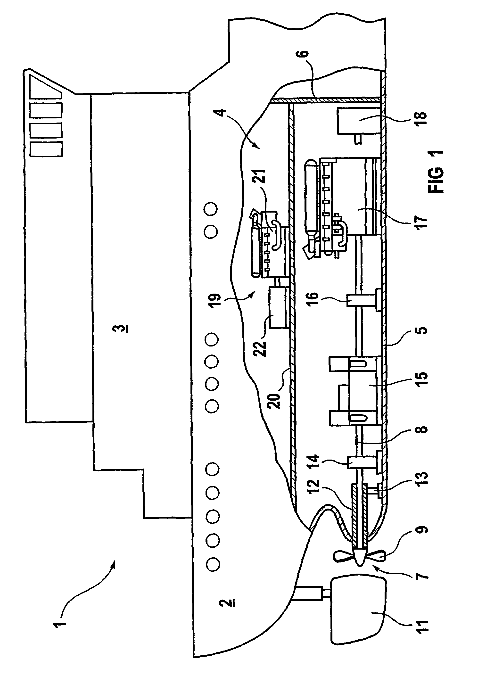
[0033]FIG. 1 shows a highly schematic illustration of a container ship 1 with a ship's hull 2 and a superstructure 3. The ship's hull 2 is cut away in the area of an engine room 4. The illustration is not to scale at all, with the only aim being to show the essential items.

[0034]The engine room 4 has an engine room deck 5 and is closed in the forward direction, in the direction of the ship's bow, by a bulkhead 6. It is closed in the rearward direction by the corresponding stern part of the ship 1. A ship propeller 7 is arranged in a known manner in an area of the stern that is shown, and is connected to a propeller shaft 8 such that they rotate together. The ship propeller 7 is what is referred to as a variable-pitch propeller, that is to say a propeller with propeller blades 9 whose pitch can be varied. A rudder 11 is fitted downstream from the propeller 9, such that it can swivel.

[0035]The propeller shaft 8 passes through a propeller shaft pipe 12, which is supported by at least o...


PUM


Abstract

A hybrid propulsion system includes a main diesel engine for driving the marine turbine and an electric motor. The electric motor has a nominal output that constitutes at least 20% of the nominal output of the main diesel engine. The electric motor remains continuously switched on and maintains, together with a variable-pitch propeller, the main diesel engine at a favorable operating point. The combination of the main diesel engine and the electric motor also allows for a more economical design or operation of the propulsion system.

Description

[0001]This application is the national phase under 35 U.S.C. § 371 of PCT International Application No. PCT / DE01 / 04556 which has an International filing date of Dec. 5, 2001, which designated the United States of America and which claims priority on German Patent Application numbers DE 100 61 578.3 filed Dec. 11, 2000, the entire contents of which is hereby incorporated herein by reference.BACKGROUND OF THE INVENTION[0002]The propulsion system for large cargo ships, for example container ships, normally provides one slow-running diesel engine for each ship propeller. This slow-running diesel engine supplies all the propulsion power for this propeller. The propulsion power of the diesel engine starts at about 10 to 15 MW. The diesel engines that are used operate on the two-stroke principle. The high power that is required and the low rated rotation speed result in a large swept volume, and thus a large physical volume with a large mass.[0003]A correspondingly large amount of space mu...

Claims


Application Information

Patent Timeline
Patent Type & Authority Patents(United States)
IPC IPC(8): B63H21/22B63H21/20
CPCB63H21/20B63H2021/202Y02T70/5236B60L2200/32
Inventor ANDERSEN, PETERRZADKI, WOLFGANG
Owner SIEMENS AG
Learn More