
Semiconductor device and manufacturing method thereof

a technology of semiconductor devices and manufacturing methods, applied in the direction of semiconductor devices, transistors, electrical devices, etc., can solve the problems of increasing the cost of the production process of semiconductor devices such as lsi, difficulty in further refinement of fabrication, and the method described above has not yet been put to practical use, and achieves excellent drain current characteristics

Inactive Publication Date: 2007-07-17
RENESAS ELECTRONICS CORP
View PDF16 Cites 5 Cited by
  • Summary
  • Abstract
  • Description
  • Claims
  • Application Information

AI Technical Summary

Benefits of technology

This approach enhances the drain current characteristics of both n-type and p-type channel transistors, reducing production costs and dislocation issues, while maintaining high reliability and performance in semiconductor devices.

Problems solved by technology

However, the required minimum fabrication size (minimum fabrication size for gate) is reduced to less than the level of the wavelength of light used for the lithography to bring about a difficulty in further refinement of fabrication.
However, when materials of different lattice constants of crystals are epitaxially grown under lattice matching as described above, the strain energy caused in the crystals increases to bring about a problem of including dislocation in the crystals at a film thickness greater than a certain critical thickness.
Further, adoption of an additional production apparatus caused by the introduction of unusual material of silicon-germanium increases the cost in the production process of semiconductor devices such as LSI.
Thus, the method described above has not yet been put to practical use.

Method used


Image

  • Semiconductor device and manufacturing method thereof
  • Semiconductor device and manufacturing method thereof
  • Semiconductor device and manufacturing method thereof

Examples


Embodiment Construction

[0048]Preferred embodiments of the present invention are to be described below. The invention is not restricted to the following embodiments but is applicable to other embodiments.

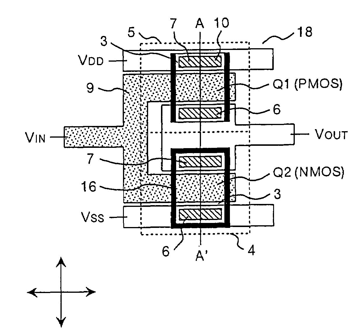
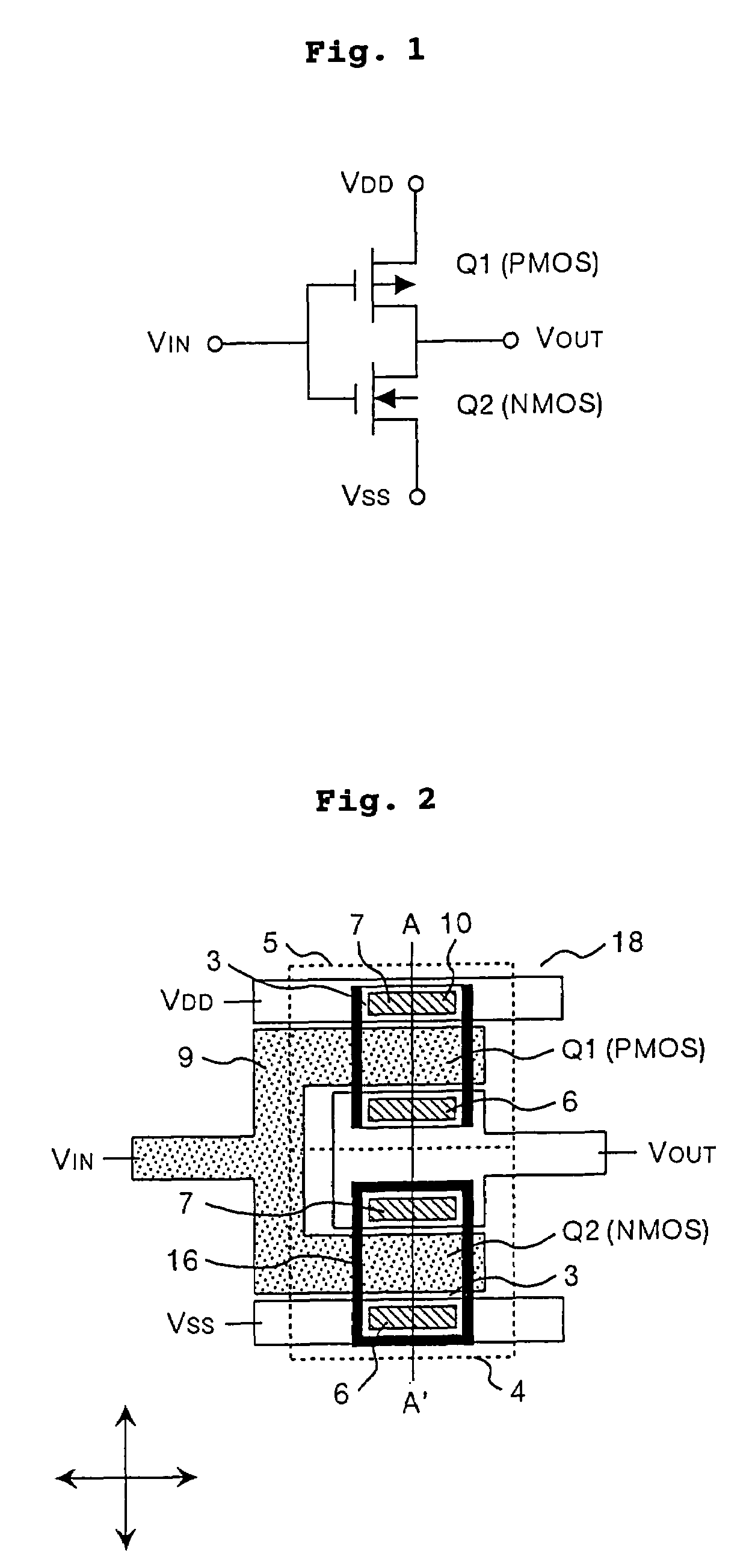
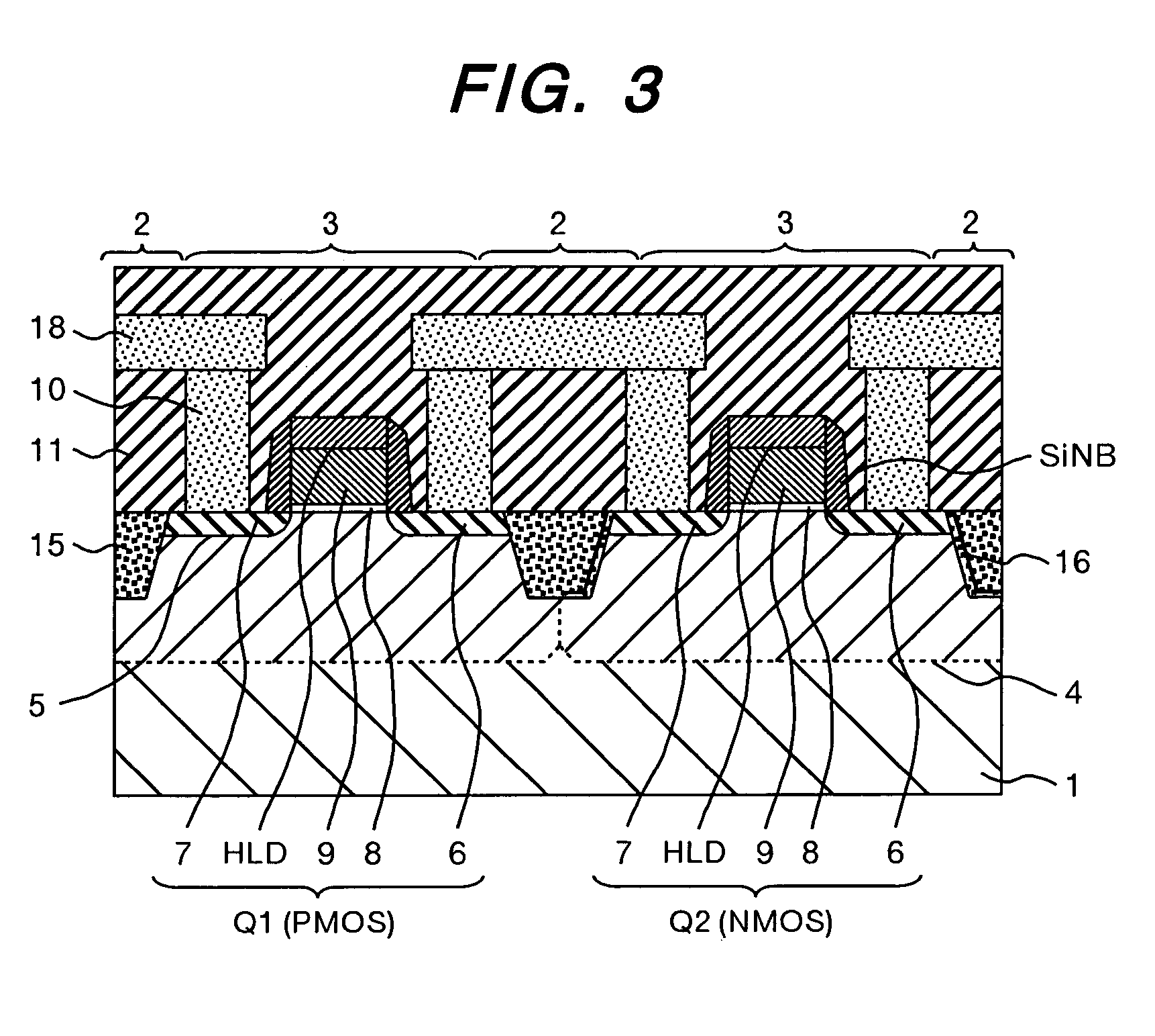
[0049]The invention is to be described by way of the first embodiment with reference to FIG. 1. FIG. 1 is an inverter circuit diagram of this embodiment; FIG. 2 is a layout of the inverter circuit; and FIG. 3 is a cross-sectional view taken along line A–A′ of FIG. 2.

[0050]As shown in FIG. 2, this embodiment comprises a p-type channel field effect transistor Q1, an n-type channel field effect transistor Q2 and interconnections for connecting the transistors electrically.

[0051]The n-type channel field effect transistor Q2 formed on a substrate (sub1) 1 comprises an n-type source (soce 1) 6, a drain (drain 1) 7, a gate electrode (poly-Si) 9 and a gate oxide film (gato-ox) 8 formed on a p-type well layer (pwell) 4. Further, the p-type channel field effect transistor Q1 comprises a p-type source (soce) 6, a dra...


PUM


Abstract

The object of the present invention is to provide a semiconductor device comprising an n-type channel field effect transistor and a p-type channel field effect transistor, which has a high degree of reliability and excellent drain current characteristics. The gist of the invention for attaining the object resides in disposing a silicon nitride film to the side wall of a trench for an active region in which the n-type channel field effect transistor is formed and disposing the silicon nitride film only in the direction perpendicular to the channel direction to the sidewall of the trench for the active region of the p-type channel field effect transistor. According to the present invention, a semiconductor device comprising an n-type channel field effect transistor and a p-type channel field effect transistor of excellent current characteristics can be provided.

Description

TECHNICAL FIELD [0001]The present invention relates to semiconductor devices and, more in particular, it relates to a semiconductor device having an n-type channel field effect transistor and a p-type channel field effect transistor.BACKGROUND ART [0002]In recent years, the processing performance required for semiconductor devices such as LSI has become severer along with the progress of information communication equipment and it has been attempted to increase the operation speed of transistors. In particular, complementary field effect transistors comprising an n-type channel field effect transistor and a p-type channel field effect transistor have been used generally since they consume less electric power. Its operation speed has been increased mainly by the refinement of the structure being supported by the progress of lithography for fabricating semiconductor devices. However, the required minimum fabrication size (minimum fabrication size for gate) is reduced to less than the l...

Claims


Application Information

Patent Timeline
Patent Type & Authority Patents(United States)
IPC IPC(8): H01L21/8238H01L21/76H01L21/762H01L21/822H01L27/04H01L27/08H01L27/092H01L27/10
CPCH01L21/76224H01L21/823807H01L29/7846H01L29/7842H01L21/823878H01L21/8238
Inventor ISHITSUKA, NORIOKUMAGAI, YUKIHIROMIURA, HIDEOIKEDA, SHUJITAKEDA, TOSHIFUMIOHTA, HIROYUKI
Owner RENESAS ELECTRONICS CORP
Learn More