Control of resin flow during molding of composite articles

Inactive Publication Date: 2007-08-14
HEXCEL COMPOSITES LTD (GB)
View PDF17 Cites 22 Cited by
  • Summary
  • Abstract
  • Description
  • Claims
  • Application Information

AI Technical Summary

Benefits of technology

[0014]In accordance with the present invention methods and assemblies are provided that control the flow of resin during molding of composite structures to eliminate or at least substantially reduce resin depletion and other unwanted resin migration. The invention is

Problems solved by technology

Although such techniques are simple and relatively inexpensive to implement in practice, the resultant product can be variable in quality and the mechanical properties of the final structure or component can often be poor.
When preparing fiber-reinforced components by a liquid resin infusion process, it has been observed that there is a tendency for the liquid resin infused into the fibrous reinforcement assembly to become depleted within certain areas of the assembly during infusion and cure.
Resin depletion is also a problem when the liquid resin infused into the fibrous reinforcement assembly is of particularly low viscosity.
The occurrence of resin depletion can be particularly disadvantageous because the final structure or component formed following the cure of the liquid resin does not contain the originally intended distribution of resin throughout its structure.
As a consequence, the mechanical properties and performance of the structure or component thus formed can be compromised, particularly in the regions where resin depletion has occurred.
In the case of a VaRTM process, for example, the areas of the assembly that have been observed to be particularly prone to the occurrence of resin depletion include the areas in the vicinity of the suction tubing that connects the vacuum pump to the mold.
In these areas, resin depletion tends to occur as a result of the suction force generated by the vacuum pump.
Resin depletion can also result from the e

Method used


Image

  • Control of resin flow during molding of composite articles
  • Control of resin flow during molding of composite articles
  • Control of resin flow during molding of composite articles

Examples


Example

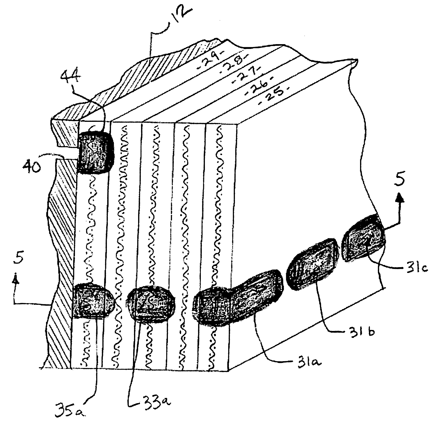
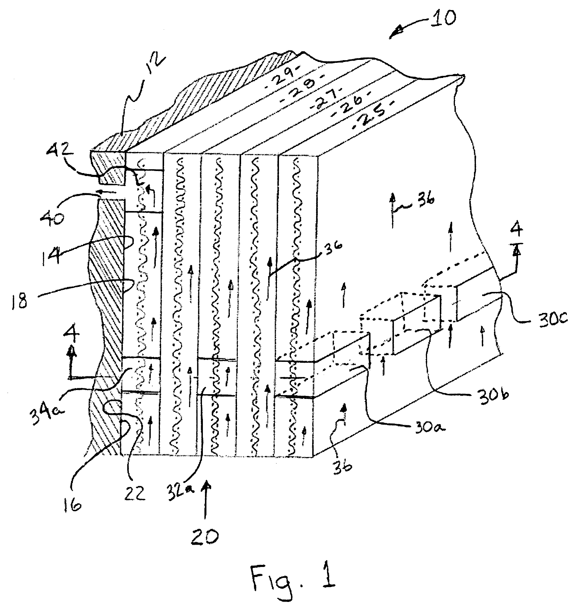
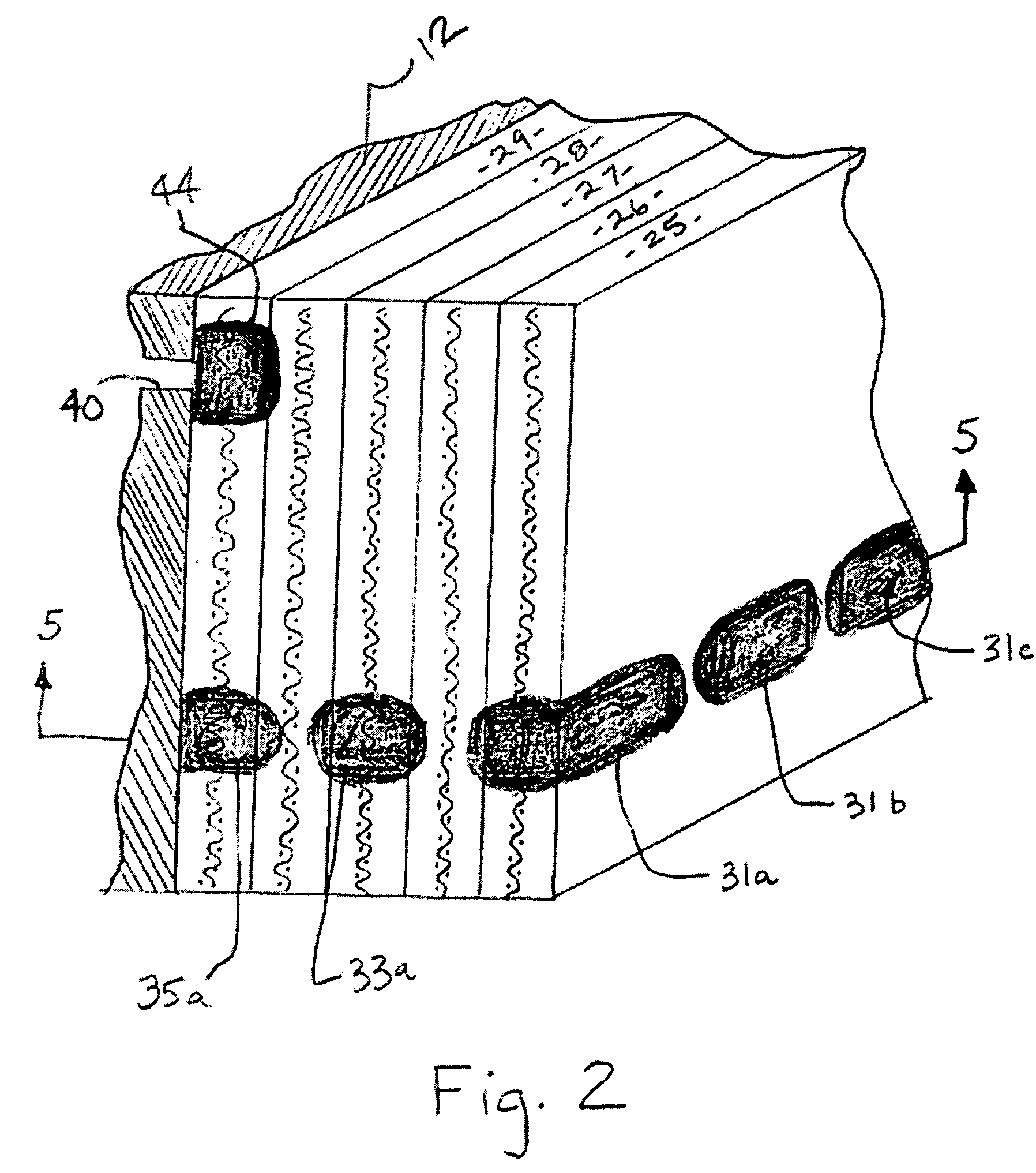
[0026]The problem of resin depletion that is observed to occur following the preparation of a fiber-reinforced composite structure or component by a resin infusion process is solved by the present invention by the selective positioning of the immobilization agent in the areas of the assembly that are prone to resin depletion (i.e. vertically inclined sections of the mould or, in a VaRTM process for example, the areas surrounding the vacuum tubing), thereby enabling the formation of a final cured structure or component having a substantially uniform distribution of resin throughout its structure. It will be appreciated that the localized immobilization of the liquid resin in the vicinity of the immobilization agent prevents, or at least substantially reduces, the tendency for resin to flow out of these areas, whether under the force of gravity or by any other driving force.

[0027]In addition to providing a solution to the problem of resin depletion, there may also be instances where t...


PUM

PropertyMeasurementUnit
Flow rateaaaaaaaaaa
Viscosityaaaaaaaaaa
Thixotropic indexaaaaaaaaaa

Abstract

The flow of resin during the molding of composite articles is controlled by forming areas of immobilized resin during the infusion of resin into the fibrous body. The immobilized resin is formed using an immobilization agent that interacts with the infused resin to form a high viscosity resin barrier that is effective in blocking the flow of non-immobilized resin. The barriers of immobilized resin are located within the fibrous body so as to control the flow of non-immobilized resin during the molding process to prevent or least reduce resin depletion and to selectively block resin flow from the mold.

Description

BACKGROUND OF THE INVENTION[0001]1. Field of the Invention[0002]The present invention relates to methods for making fiber-reinforced composite articles where uncured resin is infused into a fibrous body located in a mold to form an uncured resin impregnated fibrous body that is then cured. More particularly, the present invention involves controlling the flow of resin during the molding process to prevent or at least reduce unwanted flow or migration of the resin within the fibrous body and mold.[0003]2. Description of Related Art[0004]Fiber-reinforced composites are widely used to form structures and components for use in a range of different industries including, for example, the aerospace, transport, electronics, building and leisure industries.[0005]A common approach for the preparation of such structures or components, especially large structures or components such as boat hulls, wind turbine blades, or certain aircraft components, involves the arrangement of a fibrous reinforc...

Claims


Application Information

Patent Timeline
IPC IPC(8): B29C70/48B29C35/02B29C70/44B29C70/54
CPCB29C35/0266B29C70/443B29C70/48B29C70/546
Inventor HADLEY, PHILIP C.
Owner HEXCEL COMPOSITES LTD (GB)
Why Eureka
Try Eureka