Metal powder composition for use in selective laser sintering

a technology of laser sintering and metal powder, which is applied in the direction of process efficiency improvement, transportation and packaging, additive manufacturing, etc., can solve the problems of reduced packing density of powder composition, difficult formation of powder layer, and inability to uniformly form thin powder layer, etc., to achieve easy separation, large heat contraction, and improved shape

Inactive Publication Date: 2007-08-21
MATSUSHITA ELECTRIC WORKS LTD
View PDF16 Cites 19 Cited by
  • Summary
  • Abstract
  • Description
  • Claims
  • Application Information

AI Technical Summary

Benefits of technology

[0021]More specifically, if the proportion of the nickel and / or nickel alloy powder material is less than 5 weight percent, it is likely that the shaped object contains cracks. On the other hand, if the proportion of the nickel and / or nickel alloy powder material exceeds 35 weight percent, the shaped object is subject to large heat contraction by rapid cooling and easily separated from a shaping plate made of, for example, iron. If the proportion of the copper and / or copper alloy powder material is less than 5 weight percent, the wettability or flowability during melting, which is required for the material for selective laser sintering, is lost. On the other hand, if the proportion of the copper and / or copper alloy powder material exceeds 15 weight percent, the adhesion force between the shaped object (iron alloy containing much copper) and the shaping plate is reduced, resulting in separation of the shaped object from the shaping plate.
[0022]When at least one of a condition that the iron-based powder material includes a chrome molybdenum steel powder material and a condition that the copper alloy powder material includes a copper manganese alloy material is satisfied, the characteristics of the shaped object are further improved by addition of the graphite powder material.

Problems solved by technology
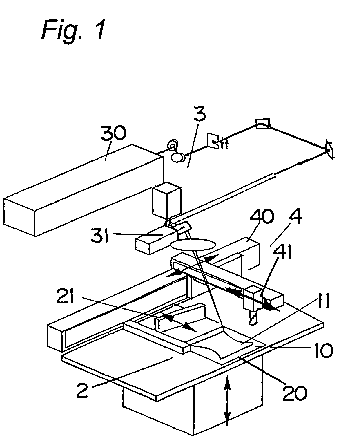
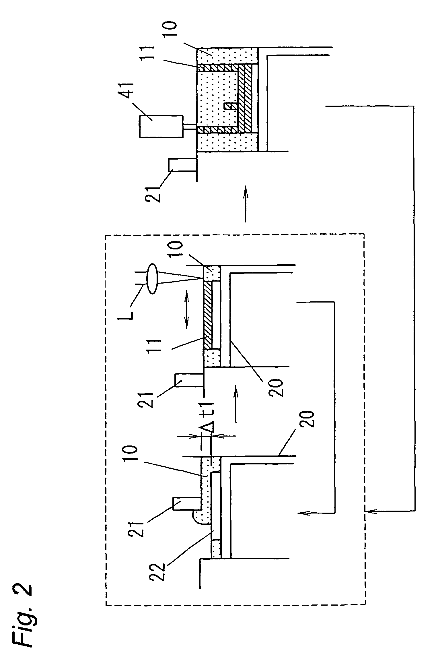
However, a too small particle diameter sometimes causes cohesion of the powder composition, resulting in a reduction in packing density of the powder composition and making it impossible to uniformly form a thin powder layer.
If such a rise is higher than the thickness of a powder layer to be formed thereon, formation of the powder layer sometimes becomes difficult.
As a matter of course, no large cracks must be present in the surface of the shaped object, and considering that a fluid medium such as cooling water is caused to flow through, for example, an injection molding die, no microcracks are desired in an internal structure thereof.

Method used


Image

  • Metal powder composition for use in selective laser sintering
  • Metal powder composition for use in selective laser sintering
  • Metal powder composition for use in selective laser sintering

Examples


examples

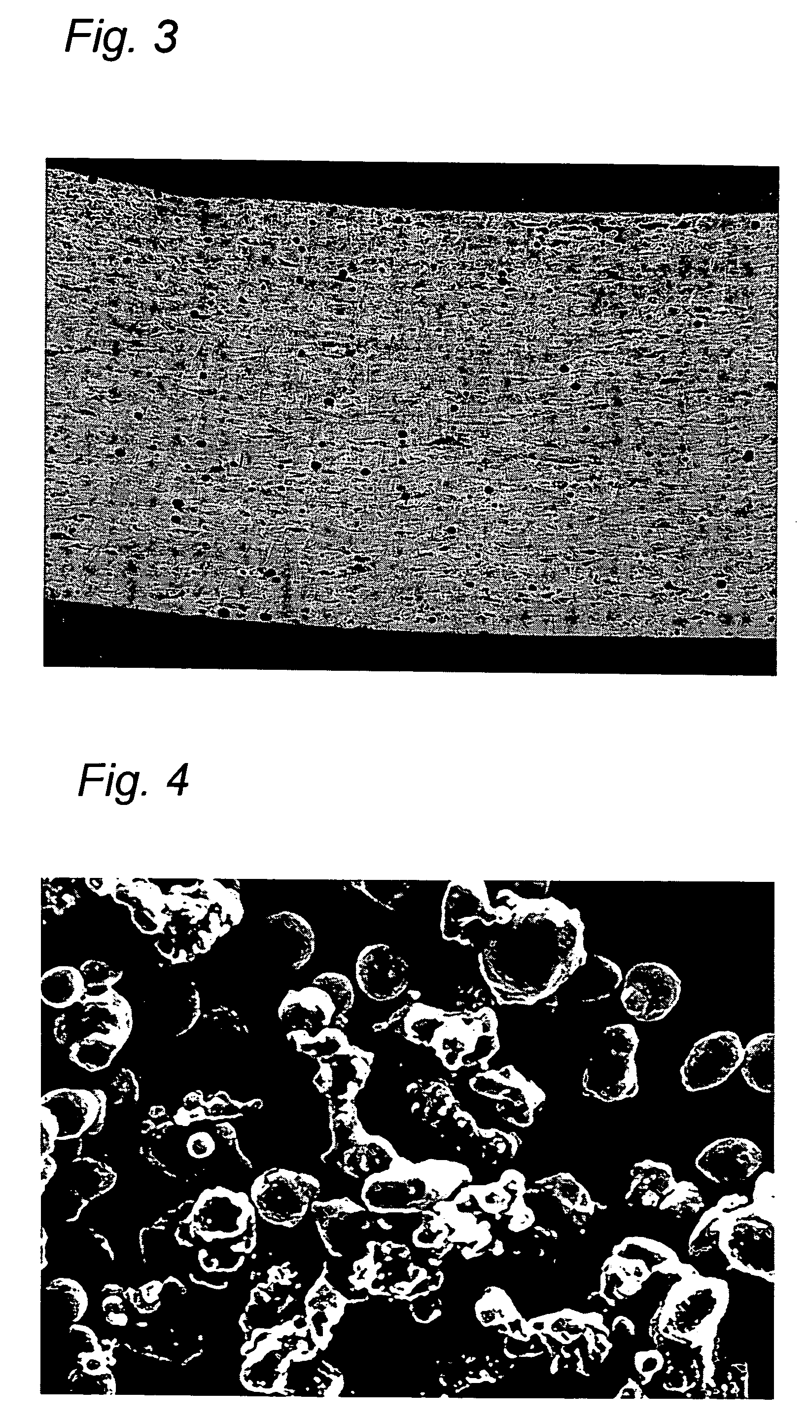
[0059]Six kinds of metal powder compositions were prepared using SCM440 (chrome molybdenum steel) powder that is mainly composed of aspherical particles and has an average particle diameter of 20 μm (see FIG. 4), Ni (nickel) powder that is mainly composed of spherical particles and has an average particle diameter of 30 μm (see FIG. 5), and CuMnNi (copper-manganese alloy made of, for example, Cu-10 wt % Mn-3 wt % Ni) powder that is mainly composed of spherical particles and has an average particle diameter of 30 μm (see FIG. 6). The six kinds of metal powder compositions were added with a varying proportion of C (graphite) as indicated below.

[0060]a) 70 wt % SCM440-21 wt % Ni-9 wt % CuMnNi

[0061]b) 70 wt % SCM440-21 wt % Ni-9 wt % CuMnNi+0.2 wt % C

[0062]c) 70 wt % SCM440-21 wt % Ni-9 wt % CuMnNi+0.4 wt % C

[0063]d) 70 wt % SCM440-21 wt % Ni-9 wt % CuMnNi+0.5 wt % C

[0064]e) 70 wt % SCM440-21 wt % Ni-9 wt % CuMnNi+0.75 wt % C

[0065]f) 70 wt % SCM440-21 wt % Ni-9 wt % CuMnNi+1.0 wt % C

[00...


PUM

PropertyMeasurementUnit
particle diameteraaaaaaaaaa
weight percentaaaaaaaaaa
particle diameteraaaaaaaaaa

Abstract

A three-dimensional object of a desired shape is made by irradiating an optical beam on a metal powder layer to form a sintered layer and by laminating such sintered layer one above another. A metal powder composition for use in making such a three-dimensional object includes an iron-based powder material, a nickel and/or nickel alloy powder material, a copper and/or copper alloy powder material, and a graphite powder material. The graphite powder material acts to enhance the wettability during melting and to reduce microcracks during solidification.

Description

BACKGROUND OF THE INVENTION[0001]1. Field of the Invention[0002]The present invention relates generally to selective laser sintering and, in particular but not exclusively, to a metal powder composition for use in selective laser sintering wherein a three-dimensional object of a desired shape is made by irradiating an optical beam on a metal powder layer to form a sintered layer and by laminating such sintered layer one above another. The present invention also relates to a method of making the metal powder composition and to a three-dimensional object shaped with the use of the metal powder composition.[0003]2. Description of the Related Art[0004]A method of making a three-dimensional object with the use of selective laser sintering is known, wherein an optical beam (directional energy beam, for example, a laser) is first irradiated on a predetermined portion of a layer of metal powder composition to form a sintered layer. The sintered layer thus obtained is then covered with a new...

Claims


Application Information

Patent Timeline
Patent Type & Authority Patents(United States)
IPC IPC(8): B22F1/00B22F1/12
CPCB22F1/0003B22F3/1055B22F1/0007B22F1/0048B22F2998/00B22F2999/00B33Y70/00B33Y30/00B33Y50/00Y02P10/25B22F1/12B22F1/09B22F1/065B22F10/28B22F10/34B22F10/38
Inventor FUWA, ISAOYOSHIDA, NORIOUENAGA, SHUSHIIWANAGA, TOSHIHARUHIGASHI, YOSHIKAZUTOGEYAMA, HIROHIKOABE, SATOSHITAKENAMI, MASATAKASHIMIZU, TAKASHI
Owner MATSUSHITA ELECTRIC WORKS LTD
Why Eureka
Try Eureka