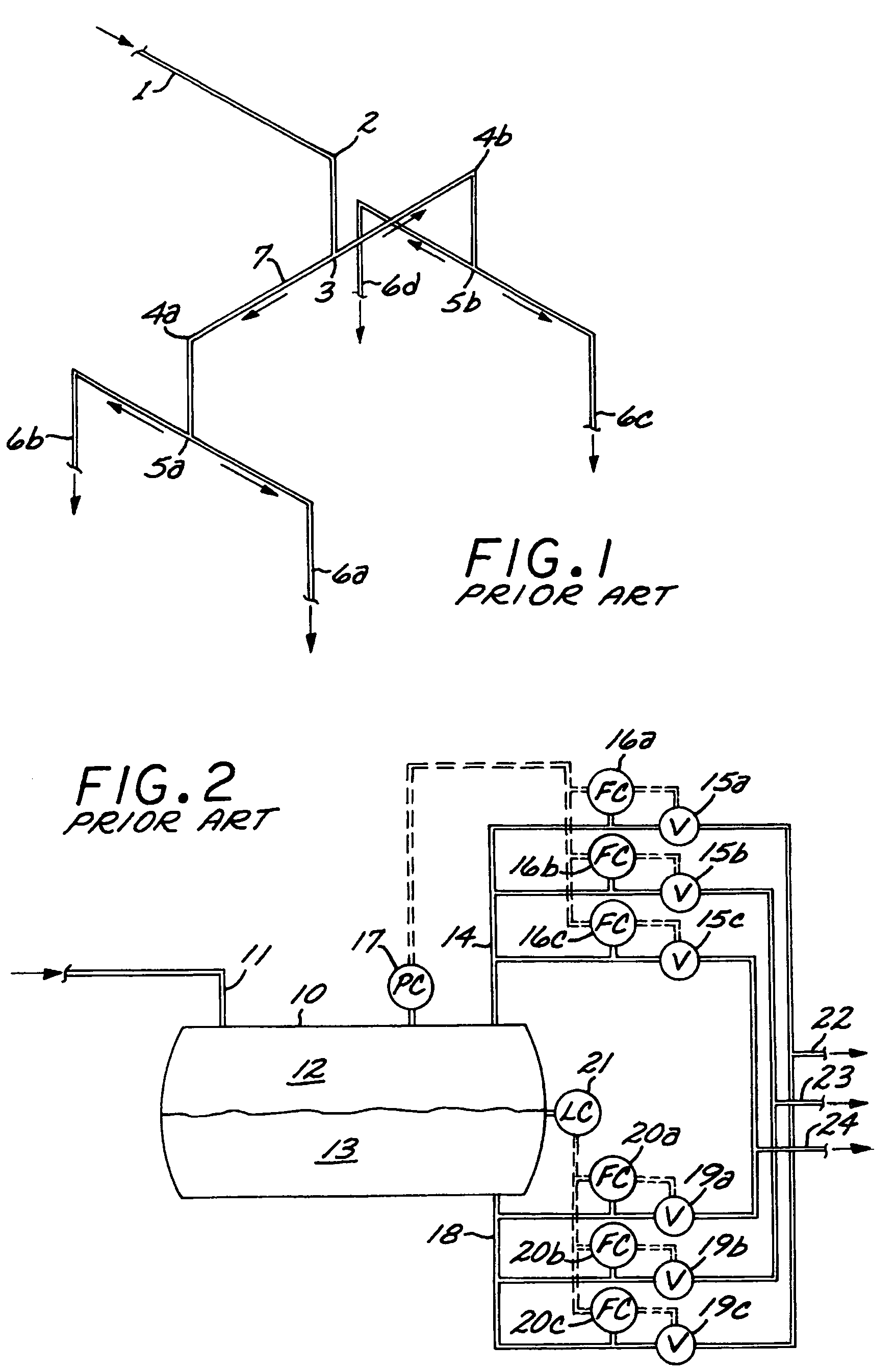
However, history has shown that this principle has failed to distribute the liquid and vapor evenly to the outlet streams, in many cases resulting in an unequal vapor-to-
liquid ratio in the outlet streams.
A major problem with the symmetrical
piping split in standard
piping tee's is that the performance of the stream split depends upon the flow regime in the upstream
pipe, and that it is not always possible to stay inside the desired “dispersed flow regime” at all relevant operating conditions.
A major limitation of the symmetrical piping split is that the flow rate of the outlet streams needs to be close to identical to avoid significant differences in the vapor-to-
liquid ratio of the outlet streams.
Another limitation is that a two-phase stream can only be split symmetrically into 2, 4, 8, 16 . . . etc. outlet streams.
It is thus not possible to make 3, 5, 6, 7, 9 . . . etc. outlet streams.
Therefore, use of static mixers disturbs the desired dispersed flow regime, if present, and results in separation of liquid and vapor, which is unwanted.
The use of static mixers introduces additional pressure drops in the process
system, which may result in additional
operating cost due to increased
power consumption in pumps and / or compressors.
Also static mixers are susceptible to
fouling caused by contaminants such as scale and
corrosion products.
As with the mixer of the first example discussed above, the mixer of the present example will tend to separate the liquid from the vapor, which is unwanted.
The stratifier collecting the fluids will only work if the vapor and liquid are distributed uniformly across the pipe cross section, which will not be the case in real applications.
However it is not clear what the driving force for uniform liquid distribution to the nozzles and outlets branches of the tee is in the case of non-uniform distribution of the liquid and vapor in the cross section of the inlet pipe.
The prediction of flow regimes in industrial applications is difficult due to the lack of accuracy of the flow regime maps.
Therefore, for instance, in a
hydrocarbon /
hydrogen system at elevated pressures and temperatures, as in a hydroprocessing unit, the flow regime maps may be inaccurate.
In addition to the uncertainty in the flow regime maps comes the uncertainty in the thermodynamic models for prediction of liquid and vapor amounts and properties.
Also piping systems in process plants are often complex systems with pipe fittings like expansions, contractions, elbows, check valves, etc.
For these three reasons it is normally not possible to accurately predict the actual flow regime in a pipe or flow channel.
Additionally, due to variations in operating conditions such as temperature, pressure, flow rate, and
chemical composition of the fluid, it is normally not possible to stay in one flow regime for all relevant operating conditions in the process unit.
For other flow regimes than Annular Flow (such as, for example,
Slug Flow, the split performance of the device may be poor.
Therefore, a certain straight pipe section is needed upstream from the splitter, which may take up additional space in the process unit.
Also there may be limitations in flow rate rangeability.
At some point the control valve goes fully open and is no longer able to control the liquid flow.
By introducing
instrumentation and
control valves, the
system is no longer as simple and robust as other two-phase flow splitters, and the pressure drop across the splitter is increased.
A higher pressure drop normally increases the
operating cost for pumping and / or compression in the process unit.
If many outlet streams are required, then the splitting system would become rather complex, and the required pressure drop would get excessive.
As already mentioned, it is hard to predict and to stay inside a certain flow regime for all relevant operating conditions.
If the flow regime during certain operating
modes is different than expected, for instance Stratified Flow, then severe maldistribution of the phases to the outlet branches is the result.
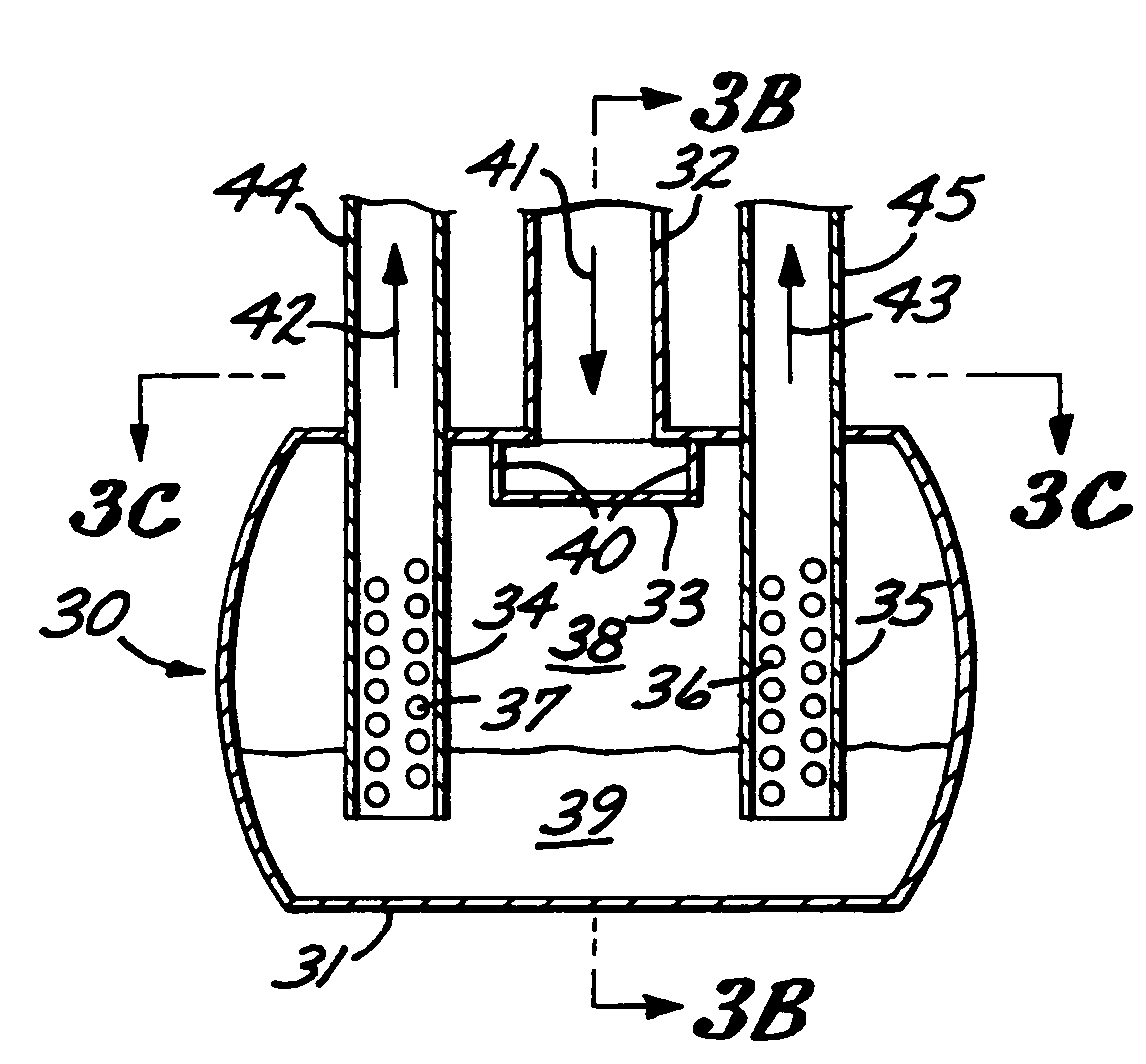
Also, the device will only generate a split stream with the desired vapor-to-liquid ratio when the liquid level in the main pipe is as foreseen.
Consequently, the device will only work for low flow velocities and for fixed vapor / liquid ratios and properties.
It is not easily understandable what the driving force for distribution of the
liquid phase is.
The liquid swirls along the inner wall of the swirl chamber, but, due to the asymmetric design, uniform flow and thickness of the
liquid layer / film are not expected.
Consequently, some of the vanes 39 are expected to collect more liquid than others, resulting in less than optimal liquid distribution to the outlet channels 37.
The main problem with this type of apparatus is obtaining a good seal between the shaft 28 and the pipe / bend 21, which is not an easy task (not an inexpensive design) in
high pressure applications like hydrocracking (up to 300 bar).
The
instrumentation for the two-phase stream splitter shown in FIG. 2 is rather complex, and as the complexity and number of components such as transmitters,
control valves and controllers are increased, the risk of failure and upsets is also increased.
Some downstream systems may be damaged if the vapor-to-liquid ratio is too high or too low during such failure or upset in the
control system.
Examples are the risk of tube rupture or
coke buildup in a furnace tube due to overheating of the tube in case the vapor-to-liquid ratio of the stream flowing inside the tube is suddenly increased.
Another example is the risk of rapid
coke build-up in parallel catalytic hydroprocessing reactors if the reactor is operated with too low a vapor-to-liquid ratio, resulting in
hydrogen deficiency even in a short period of time.
Also, the complexity of the
control system and the
large size of the separator vessel 10 result in a high cost of the splitter.
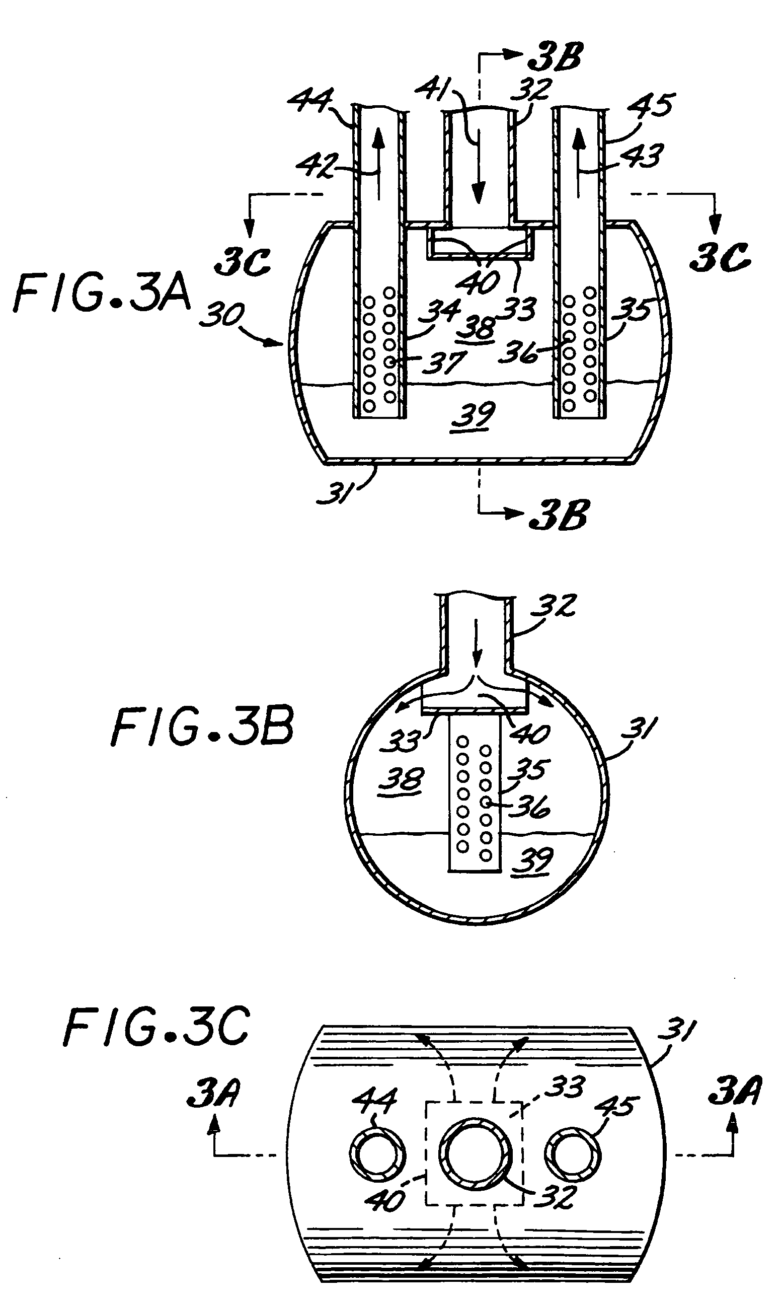
Another problem with stream splitters where the liquid head is the driving force for distribution is the limited liquid flow rangeability.
If the liquid flow is, for example, 50% higher during some operating
modes, then the liquid level will be about 2.25 times higher than the design liquid level, and liquid may thus overflow the chimneys and result in maldistribution of the liquid to the outlet streams.
At low liquid levels, the liquid distribution performance may be poor due to a large sensitivity towards
waves, non-level installation, and other fabrication tolerances.
However, if apertures at more elevations are provided, then the liquid distribution performance at the design point is reduced relative to the splitter with apertures in one elevation only.
The splitter will only work properly at the vapor flow rate and liquid flow rate for which it was designed.
The liquid and vapor flow rangeability of the splitter is insufficient for most industrial applications, which are normally characterized by significant variation in both liquid and vapor flow rate and in liquid and vapor properties like density,
viscosity, and
surface tension.

