Molten braze-coated superabrasive particles and associated methods

a superabrasive particle and braze coating technology, applied in grinding devices, other chemical processes, manufacturing tools, etc., can solve the problems of diamond particles overexposed, inability to use conventional abrasives, and inability to achieve cutting stones, etc., to improve the retention properties and improve the retention. effect of superabrasive particle retention

Inactive Publication Date: 2007-08-28
KINIK
View PDF23 Cites 61 Cited by
  • Summary
  • Abstract
  • Description
  • Claims
  • Application Information

AI Technical Summary

Benefits of technology

[0049]One advantage presented by the method of the present invention is the ability to vary or control the thickness of the reactive metal alloy coating around the superabrasive particle. Such an ability is enabled by the molten liquid state in which the alloy is applied, as will be discussed in further detail below. Specific thicknesses may be selected by one of ordinary skill in the art, as required to accomplish a particular purpose. However, in one aspect of the invention, the coating may have a thickness of at least about 1 micrometer. In another aspect, the coating may have a thickness of at least about 50 micrometers.

Problems solved by technology

In these cases, the use of conventional abrasive tools may be infeasible due to the nature of the workpiece, or the surrounding circumstances of the process.
For example, activities such as cutting stone, tile, cement, etc, are often cost prohibitive, if not impossible to accomplish, when attempted using a conventional metal saw blade.
However, because the matrix surrounding the superabrasive particles is softer than the superabrasive particles, it wears away more quickly during use, and leaves the diamond particles overexposed, and unsupported.
As a result, the diamond particles become prematurely dislodged and shorten the service life of the tool.
However, such processes are difficult and costly for a variety of reasons, including the highly inert nature of most superabrasive particles, and the high melting point of most reactive materials.
To this end, the method by which the reactive material may be applied to the superabrasives is generally limited to either solid-state reactions or gas reactions that are carried out at a temperature that is sufficiently low so that damage to the diamond does not occur.
Such processes are only capable of achieving a monolithic coating, and cannot produce an alloy coating.
While the strength of the carbide bonds yielded using these techniques generally improves particle retention over mere mechanical bonds, they still allow superabrasive particles to become dislodged prematurely.
While such processes may yield a tool that has greater grit retention than tools having no chemical bonding of the superabrasive particles, as a general matter, solid-state sintering of the braze alloy only consolidates the matrix material, and does not attain as much chemical bonding as the solid and gas state deposition techniques.
Additionally, the use of conventional braze may be limited, as it generally also serves as the matrix material for the body of the tool.
Most braze alloys are ill equipped to act as a bonding medium and simultaneously act as the matrix material, due to the specific characteristics required by each of these elements during use.
A matrix that is made of a material that is too soft may wear away too quickly and allow the superabrasive particles to dislodge prematurely.

Method used


Image

  • Molten braze-coated superabrasive particles and associated methods
  • Molten braze-coated superabrasive particles and associated methods
  • Molten braze-coated superabrasive particles and associated methods

Examples


example 1

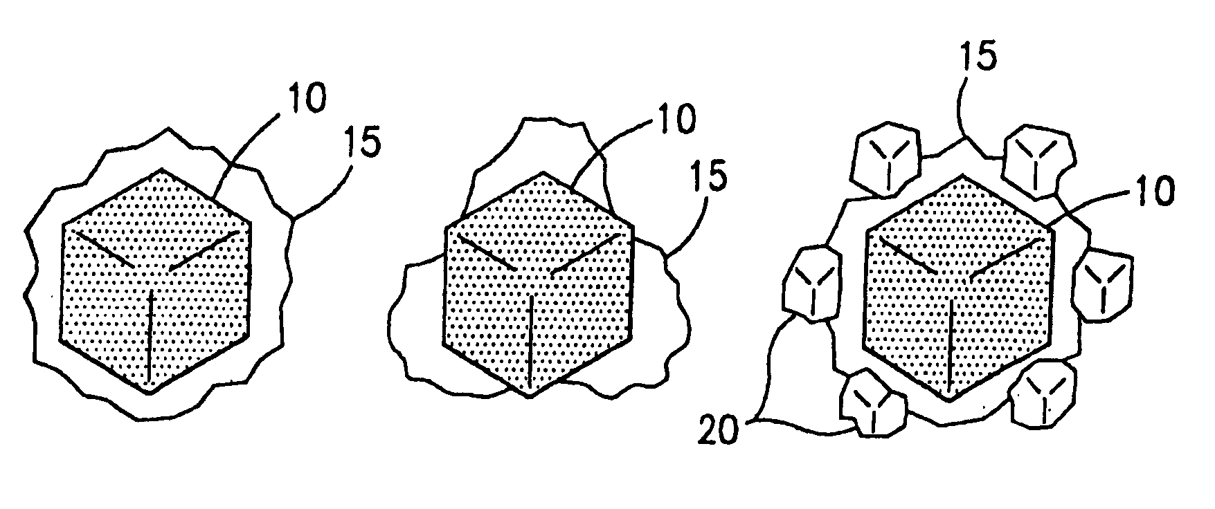
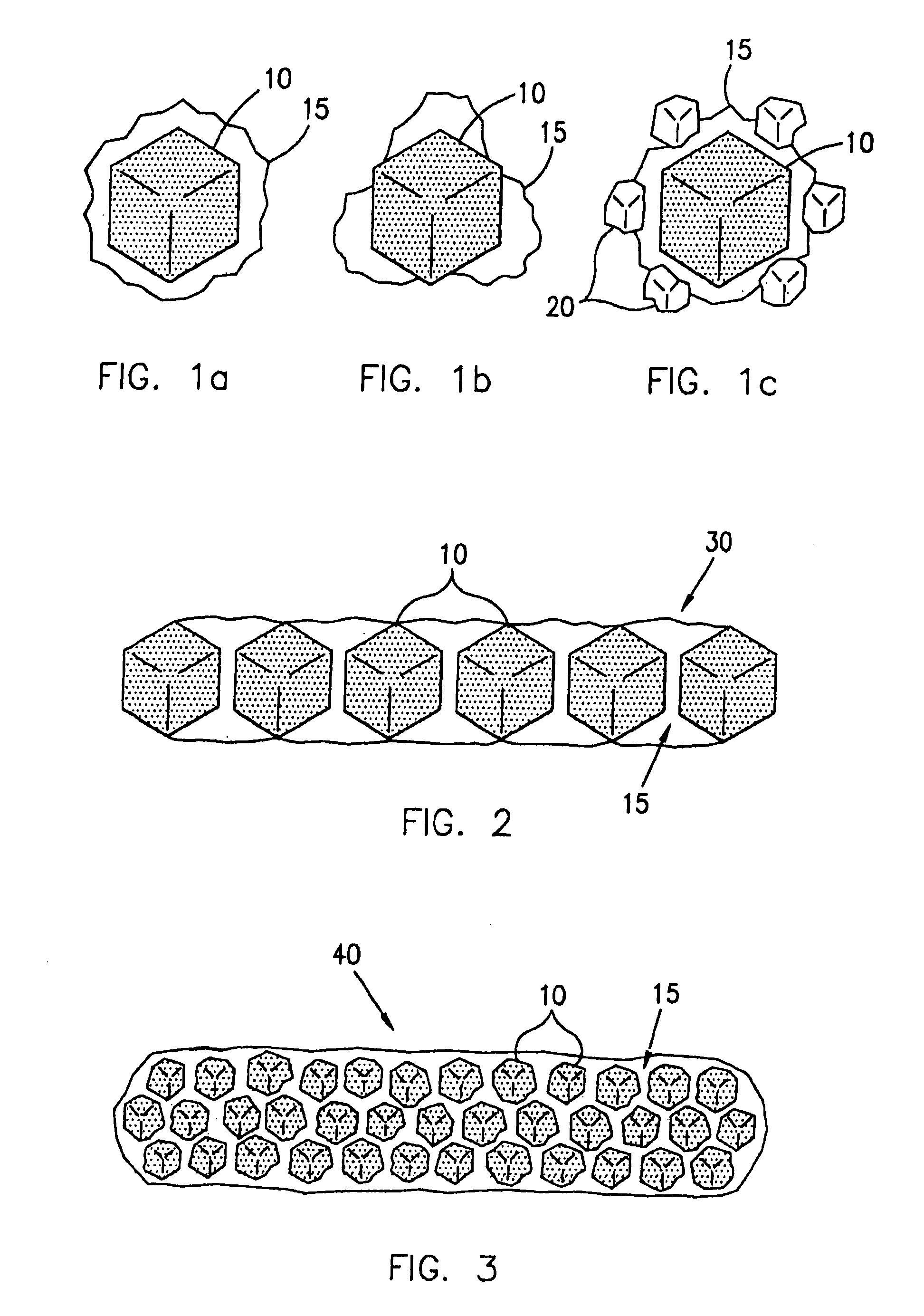
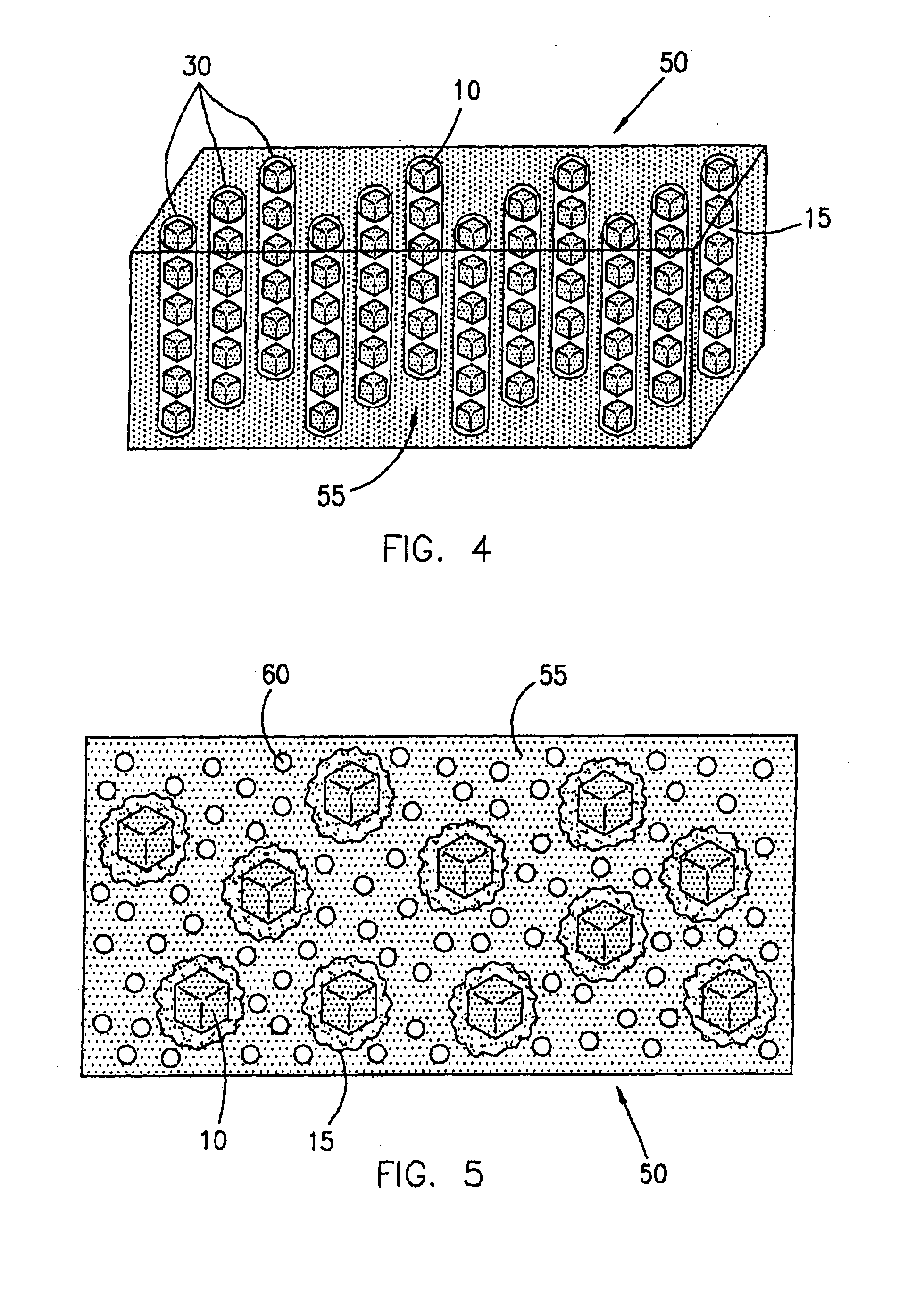
[0082]Diamond grits of 40 / 50 mesh were covered with a thin film of an acrylic binder. The binder covered diamond was then mixed with a powdered metallic alloy containing B, Ni, Cr, Si, having an average particle size of about 325 mesh, and sold under the trade name NICHROBRAZ LM® (Wall Colomnoy). The result was a braze powder wrapped diamond. These coated grits were then mixed with fine powder of Al2O3. The mixture was heated in a vacuum furnace held at 10−5 torr to a maximum temperature of about 1005° C. for approximately 17 minutes to assure that the metallic alloy coating became molten and liquefied and flowed around the diamond particles wetting them. The mixture was then cooled and retrieved from the furnace. After separating the diamond particles from Al2O3, a number of coated particles were mixed with a cobalt powder and sintered in a hot press to form rectangular segments. Some of these segments were broken by bending with pliers. The fractured surface was then viewed under ...

example 2

[0083]The same procedure as outlined in Example 1 was followed, but the Al2O3 separator powder was replaced with diamond particles having an average mesh size of from about 325 to about 400 mesh. During the heating process, the smaller diamond particles were wetted by the braze alloy coating, and became chemically bonded to the outside of the coated diamond particle. Thus, coated diamond particles having a chemically bonded metallic alloy shell with smaller diamond particles further bonded to the outside of the shell were produced. These “spiky” coated particles were incorporated into a cobalt matrix and fracture tested as above with similar results achieved.

example 3

[0084]The process of Example 2 was followed, but the smaller diamond particles were replaced with particles of SiC. The process yielded a coated diamond particle having ceramic particles bonded to the outside of the metallic coating similar to the diamond particles of Example 2. Moreover, the fracture testing yielded results similar to that of Examples 1 and 2.


PUM

PropertyMeasurementUnit
melting pointaaaaaaaaaa
melting temperatureaaaaaaaaaa

Abstract

A superabrasive particle coated with a solidified coating of a molten braze alloy that is chemically bonded to the superabrasive particle is disclosed and described. In one aspect, the reactive metal alloy may be chemically bonded to at least about 80% of an outer surface of the superabrasive particle. Various methods for making and using such a coated superabrasive particle are additionally disclosed and described.

Description

PRIORITY DATA[0001]This application is a continuation-in-part of U.S. patent application Ser. No. 10 / 254,057, filed Sep. 24, 2002, now issued as U.S. Pat. No. 6,830,598, which is incorporated herein by reference.FIELD OF THE INVENTION[0002]The present invention relates to devices that incorporate superabrasive materials, and methods for the production and use thereof. Accordingly, the present invention involves the fields of chemistry, physics, and materials science.BACKGROUND OF THE INVENTION[0003]A variety of abrasive and superabrasive tools have been developed over the past century for performing the general function of removing material from a workpiece. Actions such as sawing, drilling, polishing, cleaning, carving, and grinding, are all examples of material removal processes that have become fundamental to a variety of industries.[0004]A number of specific material removal applications require the use of superabrasive tools. In these cases, the use of conventional abrasive too...

Claims


Application Information

Patent Timeline
Patent Type & Authority Patents(United States)
IPC IPC(8): B24D18/00B05D1/18B05D7/00B24B1/00B24D3/00B24D99/00C09K3/14C22CE21B10/00
CPCC09K3/1445B24D3/00B24D99/00
Inventor SUNG, CHIEN-MIN
Owner KINIK
Why Eureka
Try Eureka