Ultrasound single-element non-contacting inspection system

Inactive Publication Date: 2007-08-28
HRL LAB
View PDF10 Cites 48 Cited by
  • Summary
  • Abstract
  • Description
  • Claims
  • Application Information

AI Technical Summary

Benefits of technology

[0022]Embodiments described herein can provide an improvement over systems based on arrays of detectors, since a single detector is lower in cost and complexity than an array of detectors. One skilled in the art will appreciate that additional elements can be added to provide electronic beam steering or focusing; however, embodiments of the present invention realize a simple effective phased array type of sensor without the need for a custom detector design.
[0023]Embodiments described herein can emulate

Problems solved by technology

One problem with laser detection systems is low sensitivity.
Consequently, the reflected beam is highly aberrated and its wavefront is mismatched with respect to the reference beam.
The system employs relatively expensive electronic tracking hardware to compensate for large amplitude, low frequency whole body motions typical in an industrial environment.
It uses optical summation for beam formation and thus requires path compensation via photorefractive wavefront compensators, which are relatively slow and introduce occasional signal dropouts.
While this system is relatively insensitive to rough workpiece surfaces, suppresses low frequency noise and provides high sensitivity without the need for active stabilization, the delay lines require long, cumbersome optical fibers to form the beam with the attendant input-output coupling losses and power limiting nonlinear effects.
Since most photorefractive crystals are slowly responding, the system can only operate over a limited bandwidth of mechanically induced background noise (whose phase noise is undesirable).
The inspection of delicate materials also requires sensitive diagnostic equipment owing to the low laser energies absorbed by the delicate material along with potential spurious modes.
However, this comes with a cost of generating wea

Method used


Image

  • Ultrasound single-element non-contacting inspection system
  • Ultrasound single-element non-contacting inspection system
  • Ultrasound single-element non-contacting inspection system

Examples


Embodiment Construction

[0033]The presently disclosed technology will now be described more fully hereinafter with reference to the accompanying drawings, in which preferred embodiments are described. The presently disclosed technology may be embodied in many different forms and should not be construed as limited to the embodiments set forth herein. Further, the dimensions of certain elements shown in the accompanying drawings may be exaggerated to more clearly show details. The present invention should not be construed as being limited to the dimensional relations shown in the drawings.

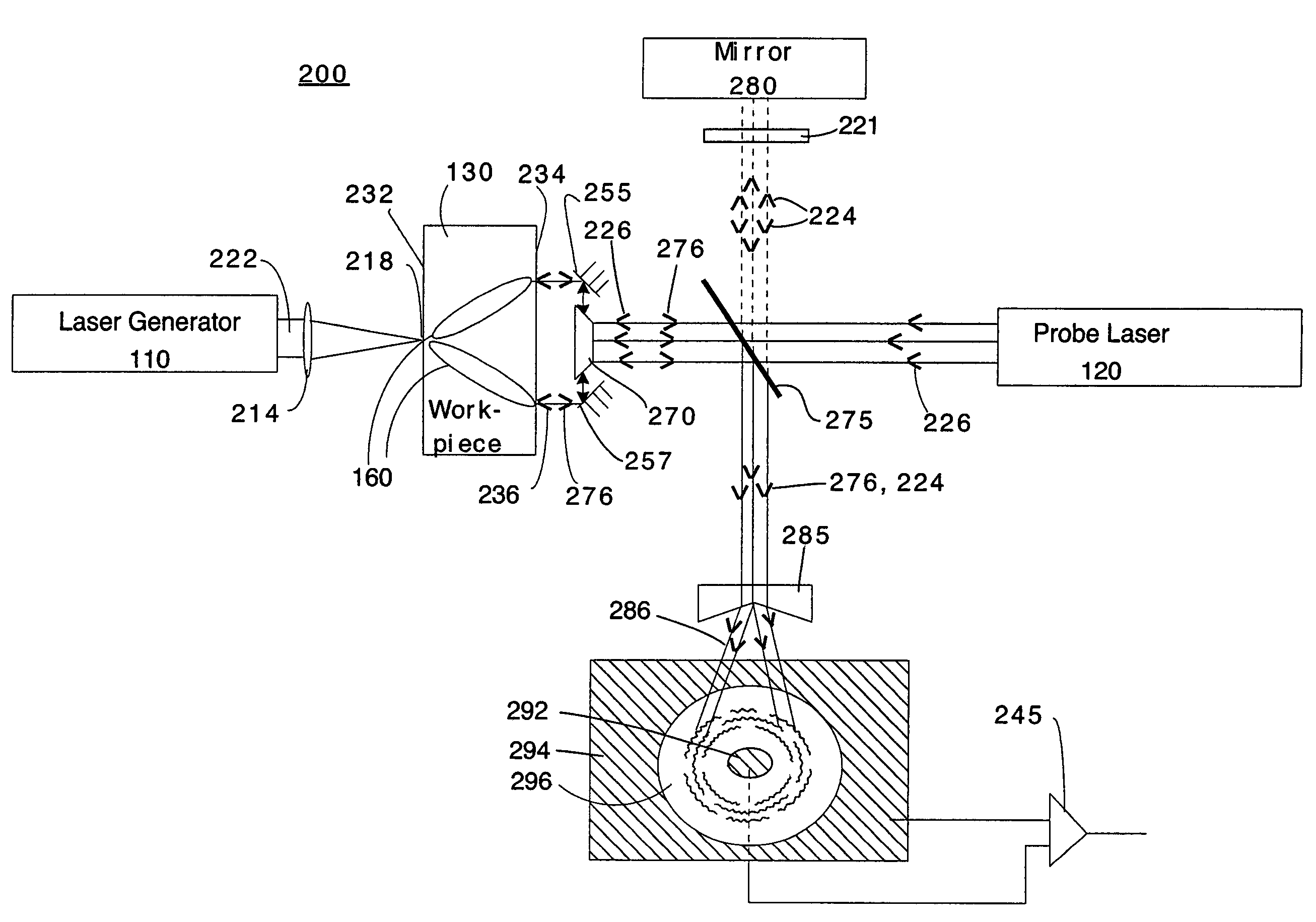
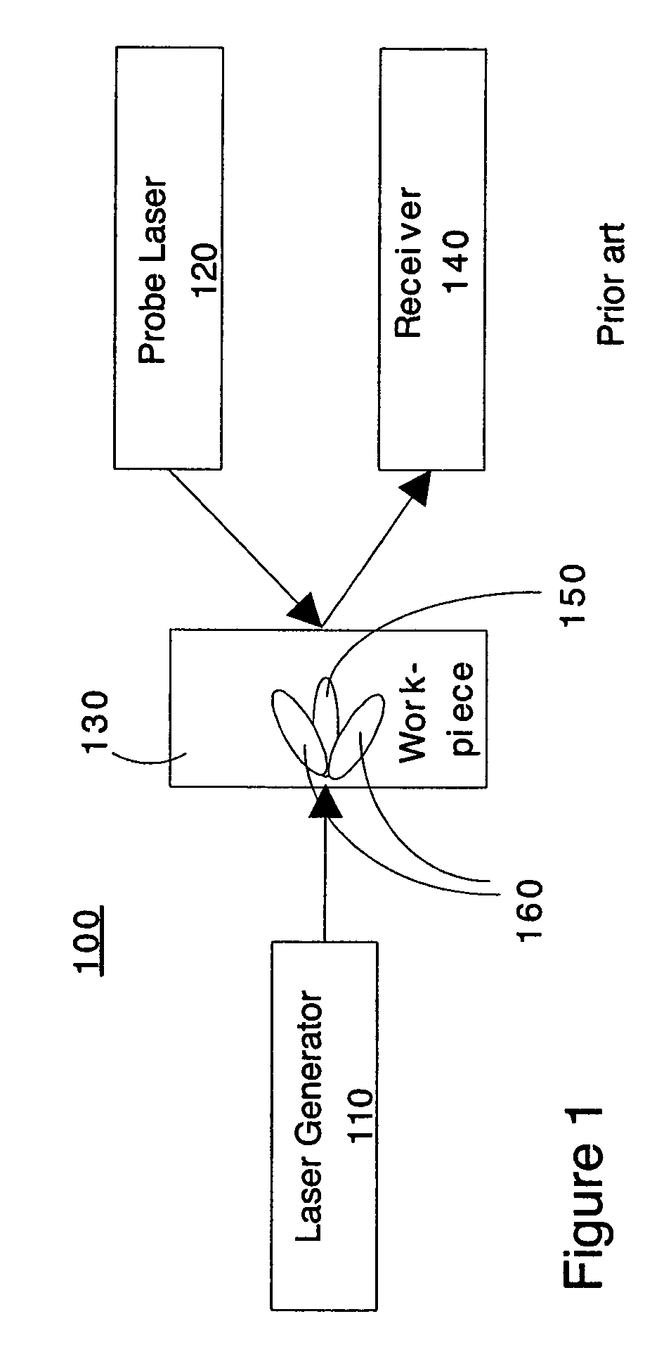
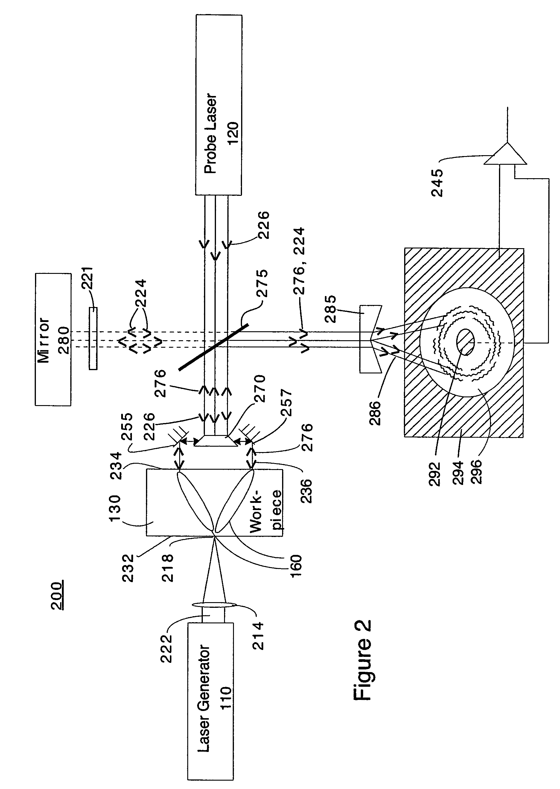
[0034]FIG. 1 depicts a cross-sectional, simplified view of the architecture of a conventional prior art ultrasonic inspection system. The ultrasonic inspection system 100 of FIG. 1 comprises a laser generator 110 for generating an ultrasound signal directed toward a workpiece 130, a probe laser 120 for sampling the ultrasound from the workpiece 130 and a receiver 140. The beam from the laser generator 110 may be focused ont...


PUM


Abstract

A laser ultrasonic inspection apparatus and method which enables remote sensing of thickness, hardness, temperature and/or internal defect detection is disclosed. A laser generator impinges a workpiece with light for generating a thermo-elastic acoustic reaction in a workpiece. A probe laser impinges the workpiece with an annularly-shaped probe light for interaction with the acoustic signal in the workpiece resulting in a modulated return beam. A photodetector having a sensitive region for detecting an annularly-shaped fringe pattern generated by an interaction of a reference signal and with the modulated return beam at said sensitive region.

Description

BACKGROUND[0001]1. Technical Field[0002]The present disclosure relates generally to ultrasonic non-contacting inspection systems and more particularly to ultrasonic non-contacting inspection systems requiring only a single element sensor to realize high spatial resolution acoustic imagery in one embodiment, and spatially averaged probing of material properties in another embodiment[0003]2. Description of Related Art[0004]Ultrasonic waves are commonly used to probe a variety of materials (workpieces), particularly for thickness gauging and flaw detection. The sound waves have usually been generated with a contact piezoelectric transducer (PZT). The launched waves propagate through the material, reflecting from interfaces (in thickness gauging applications) or internal features (in flaw detection applications). The scattered sound propagates back to the surface of the workpiece, causing the surface to vibrate at the ultrasound frequency. This vibration has been previously detected wit...

Claims


Application Information

Patent Timeline
IPC IPC(8): G01B11/02
CPCG01B11/06G01B17/02G01N21/1702G01N29/043G01N29/2418G01N2291/02827G01N2291/02854G01N2291/0421
Inventor PEPPER, DAVID M.O'MEARA, THOMAS R.
Owner HRL LAB
Why Eureka
Try Eureka