Acid gas removal

a technology of acid gas removal and absorption capacity, applied in the direction of vortex flow apparatus, hydrogen sulfide, single-direction vortex, etc., can solve the problems of insufficient acid gas absorption capacity of existing plants, and inability to effectively remove the acid gas. , to achieve the effect of reducing or eliminating the co-absorption of carbon dioxide and/or the entrainment of hydrocarbons, increasing the acid gas absorption capacity of existing

Active Publication Date: 2007-09-25
STATOIL ASA PETRO SA (NO)
View PDF13 Cites 24 Cited by
  • Summary
  • Abstract
  • Description
  • Claims
  • Application Information

AI Technical Summary

Benefits of technology

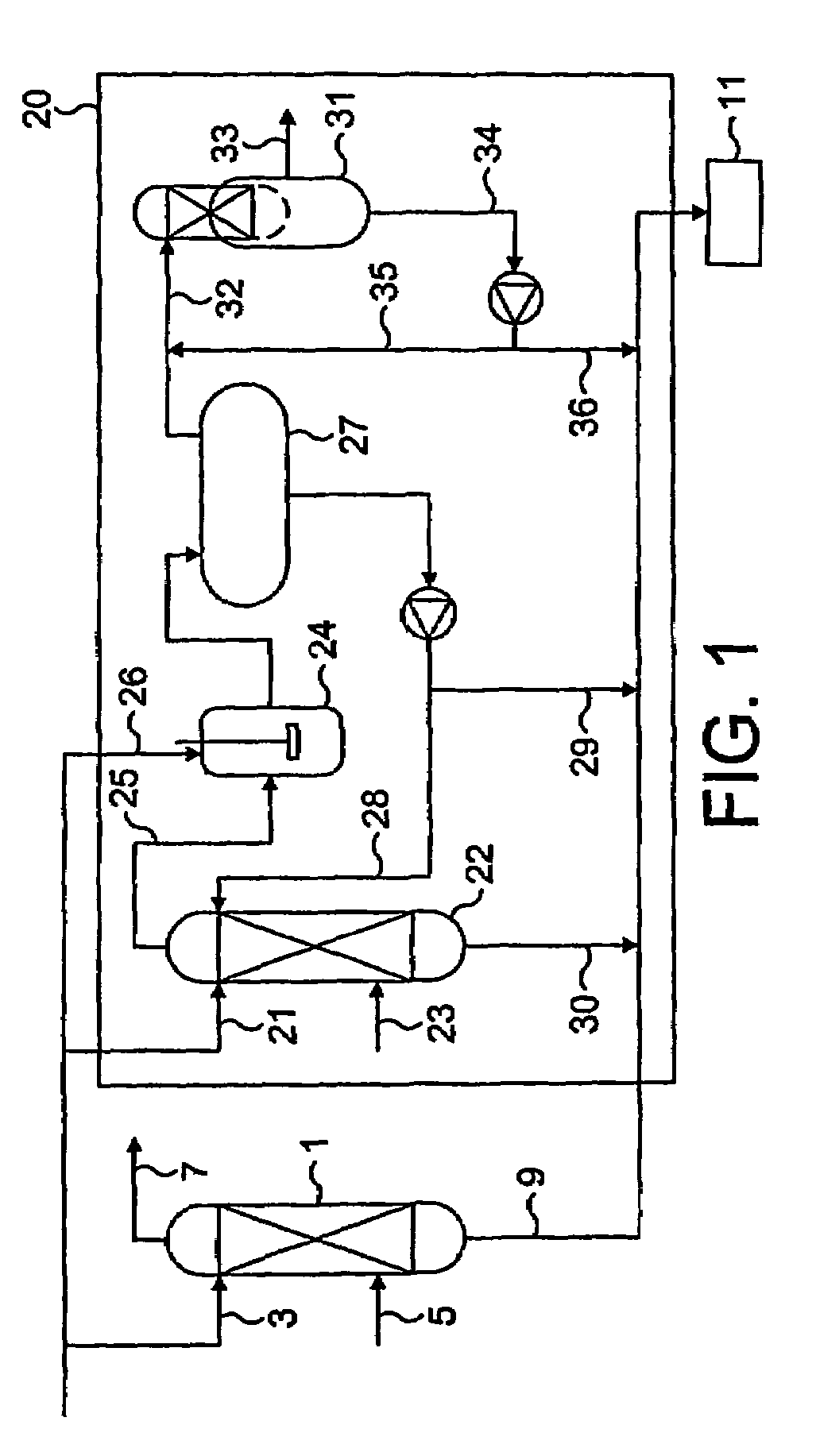
[0007]The present invention provides a method for increasing the acid gas absorption capacity of an existing plant and thereby de-bottlenecking plants. In addition, the present invention provides a process in which the co-absorption of carbon dioxide and / or the entrainment of hydrocarbons is reduced or eliminated.
[0008]There is therefore a need for a process in which the co-absorption of carbon dioxide and / or the entrainment of hydrocarbons is reduced or eliminated. The present invention provides a method for doing this.
[0010]Using the method of the present invention, significant reductions in the quantity of hydrocarbon entrainment in the liquid stream can be obtained without any loss in performance of acid gas absorption. It is therefore possible to use semi-loaded liquid streams which have hydrocarbons entrained for the treatment of gas streams for the absorption of acid gas components. The method also provides benefits in the removal of the hydrocarbons thereby minimising problems further downstream where hydrocarbons may block the system or cause a further bottleneck.

Problems solved by technology

However changes to the feed conditions cause problems in operation and the absorber may have to be substantially modified to attain satisfactory or optimum performance.
Modifications to the existing absorption columns and the associated apparatus are expensive and time consuming and many of the above variables can change on a regular basis.
However, this is not always appropriate and can introduce secondary problems such as regeneration considerations and corrosion problems.
This option only has limited capacity for increasing the acid gas removal due to the overall size of the column.
A further problem with plants which have become bottlenecked is that hydrocarbons and carbon dioxide may become entrained and / or absorbed in the acid gas solvent (e.g. amine) and are therefore subsequently fed to the downstream treatment units such as a Claus sulphur recovery unit.
These additional components in the feed to the Claus unit reduce the efficiency of the de-sulphurisation plant and may cause an additional bottleneck further down the process.
This may overload the existing pumps and require the addition of more or replacement pumps.

Method used


Image

  • Acid gas removal
  • Acid gas removal
  • Acid gas removal

Examples


first embodiment

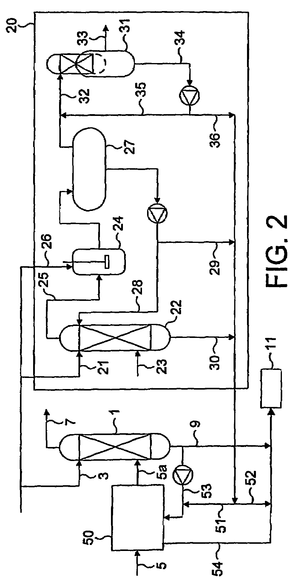
[0053]FIG. 4a shows a contactor which may be the first of the series mixers in contactor unit 50. The contactor 201 comprises a gas stream inlet 202, a liquid stream inlet 203 and an outlet 204. The gas stream is supplied to the gas stream inlet which leads to a converging pipe section 205. The converging pipe section 205 accelerates the gas stream as it passes the liquid stream inlet 203 to the end of the pipe section 205 where there is a sharp edge 206. Downstream of this sharp edge 206 there is a reaction zone 207 where the gas and liquid are preferably formed into a homogeneous mixture.

[0054]The liquid is supplied to the liquid stream inlet 203 from where it is fed in a controlled manner to the inside of the converging pipe section 205. The liquid is presented to the pipe in the form of an annulus around the inner surface of the pipe. The initial phase velocity of the liquid exposed to the gas stream is governed by the liquid flowrate, the gap distance 208 and the annulus distan...

second embodiment

[0057]FIG. 4c shows a contactor suitable for use in the method of the present invention as the first mixer in contactor unit 50. Contactor 220 comprises a gas stream inlet 222, a liquid stream inlet 223 and an outlet 224. The gas stream is supplied to the gas stream inlet which leads to a converging pipe section 225 for accelerating the gas stream. At the end of the converging pipe section there is a sharp edge 226 downstream of which there is a reaction zone 227 where the gas and liquid are preferably formed into a homogeneous mixture. One difference between the contactor of FIG. 4a and that of FIG. 4c is the relative location of the liquid inlet to the annulus of liquid. In this case, the liquid is supplied to the inlet 223 from where it passes through the passages 223a and 223b to a reservoir 223c which passes round the circumference of the pipe. The liquid then passes out through the channel 223d which again passes round the whole circumference of the pipe (see FIG. 4d) to an an...


PUM

PropertyMeasurementUnit
diameteraaaaaaaaaa
diameteraaaaaaaaaa
diameteraaaaaaaaaa

Abstract

The use of turbulent contactors to simultaneously absorb selected acid gas components from a gas stream and flash off hydrocarbons entrained in a liquid stream which include a solvent or reagent for the selected gas component. In particular, the method comprises feeding the gas stream and liquid stream into a first contactor where they are contacted co-currently and subjected to turbulent mixing conditions, and passing the multi-phase flow from the first contactor to a second contactor. The multi-phase flow from the second contactor is subsequently separated into a gas phase and a liquid phase.

Description

RELATED APPLICATION[0001]This application claims priority to PCT Application No. PCT / GB02 / 05878 filed Dec. 20, 2002 and Great Britain Application No. 0130792.5 filed Dec. 21, 2001.TECHNICAL FIELD[0002]The present invention relates to a method for the simultaneous removal of acid gas components and hydrocarbons from a gas stream. In particular the invention relates to the selective removal of H2S over CO2 using an amine.BACKGROUND ART[0003]Conventionally, acid gas components are removed using large absorption columns. These columns are designed to handle a gas feed at a certain flow rate and acid gas content. However changes to the feed conditions cause problems in operation and the absorber may have to be substantially modified to attain satisfactory or optimum performance. Problems where modification is required include, but are not limited to: an increase in the volumetric sour gas flow rate; a requirement for a lower acid gas concentration in the treated gas; a lower solvent circ...

Claims


Application Information

Patent Timeline
Patent Type & Authority Patents(United States)
IPC IPC(8): B01D45/12B01D47/10B01D53/14B01D3/06B01F3/04B01F5/04B01F5/06B01F13/10
CPCB01D3/06B01D53/1425B01D53/1431B01F3/04049B01F3/0446B01F5/0473B01F5/049B01F5/0644B01F5/0646B01F5/0652B01F5/0682B01F5/0689B01F13/1027B01F2013/1052Y02C10/06Y10S261/54Y02C20/40B01F23/2132B01F23/232B01F25/3141B01F25/31432B01F25/4323B01F25/433B01F25/4335B01F25/45B01F25/45211B01F33/834B01F33/821B01F23/2326
Inventor LINGA, HARALDNILSEN, INGE SVERRE LUNDNILSEN, FINN PATRICKHOYLAND, TROND OLAV
Owner STATOIL ASA PETRO SA (NO)
Why Eureka
Try Eureka