

Measuring device
a measuring device and sensor technology, applied in the field of apparatus, can solve the problems of complex manufacturing of sensors and some problems in the embodiment of sensors, and achieve the effect of manufacturing at moderate cos
- Summary
- Abstract
- Description
- Claims
- Application Information
AI Technical Summary
Benefits of technology
Problems solved by technology
Method used
Image

Examples
first embodiment
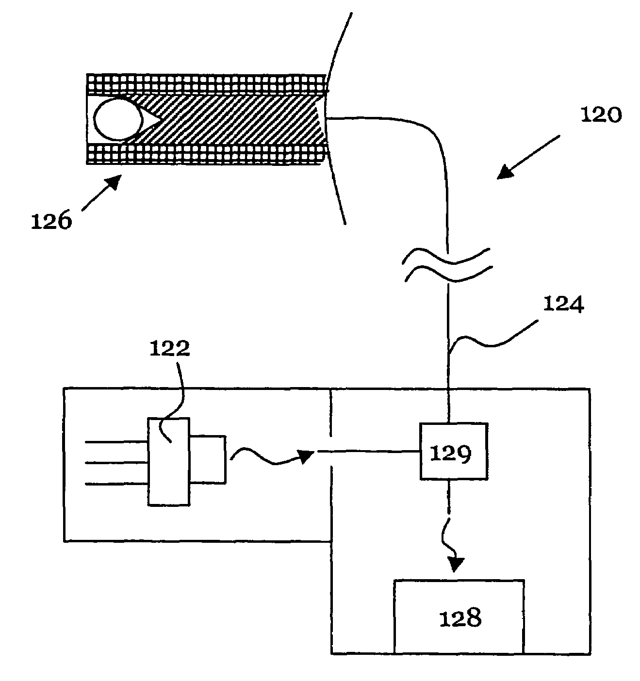
[0060]The tip 126 represented in FIG. 12 comprises a resonator and corresponds to the sensor (FIG. 1). The light is coupled to the resonator. The light guide 10 serves simultaneously for decoupling of light from the optical resonator. Said light is than guided in the opposite direction to the evaluation unit 128. Here, the directional coupler 129 guarantees that only light guided backward through the light guide 124 reaches the evaluation unit 128.
[0061]The measuring process can now be carried out as described in DE 199 60 370 by coupling light of a certain spectral range emitted by the laser diode to the light guide. The spectral range should correspond to at least one mode spacing of the resonator. The light decoupled from the resonator is than evaluated with a frequency selective evaluation device such as an optical spectrometer.
[0062]Alternatively, it is also possible to use a tunable laser diode 122. The measurement is than carried out by changing the frequency of the tunable l...
second embodiment
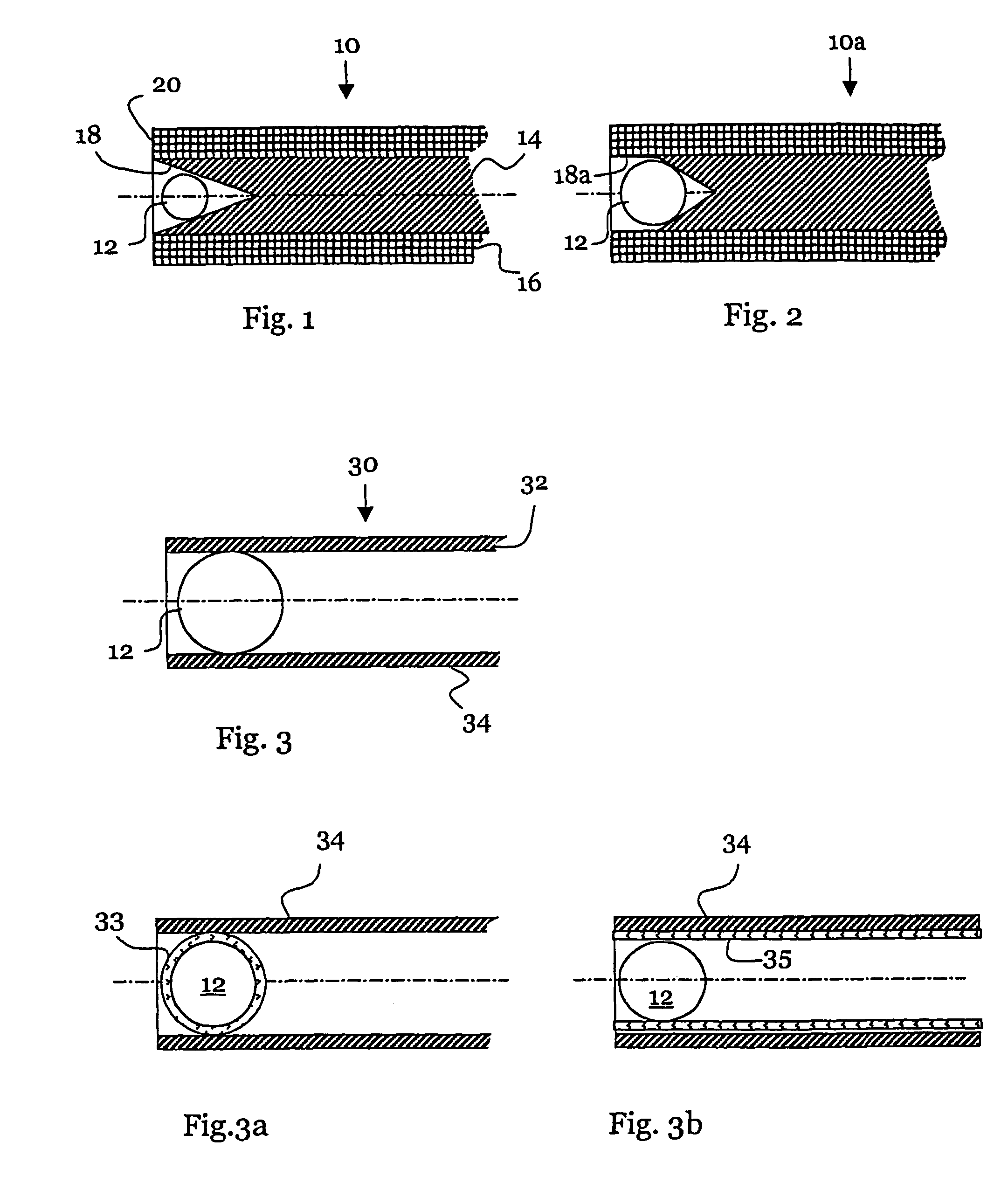
[0064]In the second embodiment according to FIG. 2, the same multimode fiber 10 is used as in FIG. 1. The resonator 12 shows a slightly larger diameter of about 90 μm. The light guide 10a exhibits a cutout 18a with a cylindrical part in the front area and a conical part in the rear area.
[0065]The first and second embodiments are identical with respect that advantageous coupling of the light guide and the resonator via the ring-shaped area takes place. Resonators of different sizes can by placed in conical cutout 18 and in the rear conical cutout 18a, respectively. The resonators are always in contact with the conical surface area of the cutout. If the cutout is completely cylindrical (not shown) or partly cylindrical (as in FIG. 2), a predetermined gap between the resonator and the light guiding core 14 can be guaranteed if a resonators of appropriate size is used.
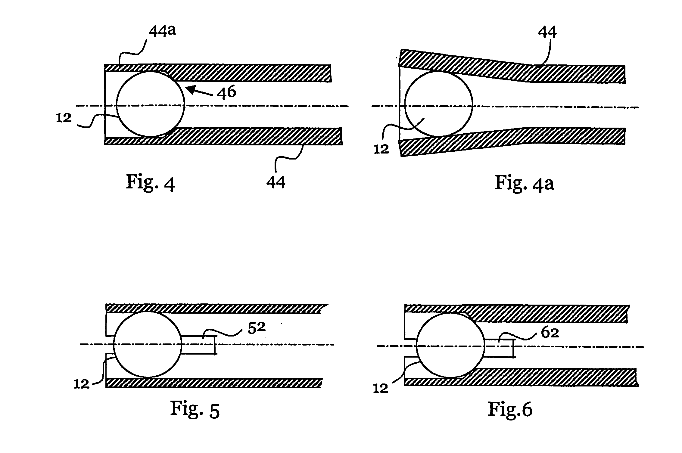
[0066]In FIGS. 3 through 9 sensors are shown each with one resonator 12 coupled to optical hollow waveguides. The hollow...
third embodiment
[0067]In FIG. 3 a sensor 30 is shown, where the spherical resonator 12 is inserted in the interior of a hollow waveguide 34. The resonator 34 is fixed by clamping within the light guide 34 and is in contact with the light guiding material 32 by a ring-shaped surface line. Especially, if the resonator is fixed by clamping in a hollow waveguide the use of an elliptical resonator (not shown) is advantageous. In this case, the expansion in longitudinal direction may be larger than in the transverse direction. A change in size of the resonator affects for example primarily the longitudinal direction. The contact line and the clamping between the hollow waveguide and the resonator remain nearly unchanged.
[0068]The sensor 30 can be manufactured by insertion of the resonator through the front opening. The resonator is adjusted to the inner diameter of the light guide 34. The resonator 12 is completely contained in the interior. Optical coupling and decoupling takes place along the full cont...
PUM
 Abstract
Description
Claims
Application Information