Method and apparatus for a high resolution downhole spectrometer

a scanning spectrometer, high-resolution technology, applied in the direction of optical radiation measurement, survey, borehole/well accessories, etc., can solve the problems of waste of expensive rig time, sample may be useless, invalid samples, etc., and achieve high resolution, simple, robust and versatile

Inactive Publication Date: 2007-10-09
BAKER HUGHES INC
View PDF16 Cites 41 Cited by
  • Summary
  • Abstract
  • Description
  • Claims
  • Application Information

AI Technical Summary

Benefits of technology

[0016]The present invention provides a simple, robust, and versatile high-resolution spectrometer that is suitable for downhole use. The present invention provides a method and apparatus incorporating a spinning, oscillating or stepping optical interference filter to change the angle at which light passes through the filters after passing through a sample under analysis downhole. As each filter is tilted, the color or wavelength of light passed by the filter changes. Black plates are placed between the filters to isolate each filter's photodiode. The spectrometer of the present invention is suitable for use with a wire line formation tester, such as the Baker Atlas Reservation Characterization Instrument to provide supplemental analysis and monitoring of sample clean up. The present invention is also suitable for deployment in a monitoring while drilling environment. The present invention provides a high resolution spectometer which enables quantification of a crude oil's percentage of aromatics, olefins, and saturates to estimate a sample's gas oil ratio (GOR). Gases such as CO2 are also detectable. The percentage of oil-based mud filtrate contamination in a crude oil sample can be estimated with the present invention by using a suitable training set and chemometrics, a neural network, or other type of correlation method.

Problems solved by technology

Contaminated samples yield invalid results when trying to determine the properties of a hydrocarbon bearing formation.
They do not want to pump unnecessarily long and waste very expensive rig time.
If the contamination is more than about 10%, the sample may be useless.
In such cases, the PVT properties measured in the lab cannot be corrected back to true reservoir conditions because of this excessive contamination.
In the down-hole environment, photodetectors are utilized and must operate at high ambient temperatures, thus, they are very noisy and generate very little signal.
Moreover, dirty or contaminated samples of flowing streams of crude oil containing scatterers such as sand particles or gas bubbles tend to add noise to the system.
Photodetectors and their amplifiers almost always have some thermal noise and drift, which limit the accuracy of a spectral reading.
As operating temperature increases, noise and drift increase dramatically at the same time that photodetector signal becomes significantly weaker.
Button et al. does not enable the possibility of a full rotation or control of the angular deviation.
The down-hole environment is difficult for operating sensors.
Reasons include limited space within a tool's pressure housing, elevated temperatures, and the need to withstand shock and vibration.
These epoxy replicas soften and creep at high temperature, which causes a distortion in the spectrum and a loss in light intensity.
Moreover, the price of an all-glass master grating ($50-100K) is prohibitively expensive.
Known laboratory spectrometers typically utilize Fourier Transform (FT) spectroscopy which are unsuitable for down-hole applications.
FT spectrometers are large (2-3 feet long, 1-2 feet wide), heavy (200-300 lbs), mechanically and electronically complicated, and must maintain perfect alignment of all their optical components to work properly, which is why they are typically built on a very rigid framework.

Method used


Image

  • Method and apparatus for a high resolution downhole spectrometer
  • Method and apparatus for a high resolution downhole spectrometer
  • Method and apparatus for a high resolution downhole spectrometer

Examples


Embodiment Construction

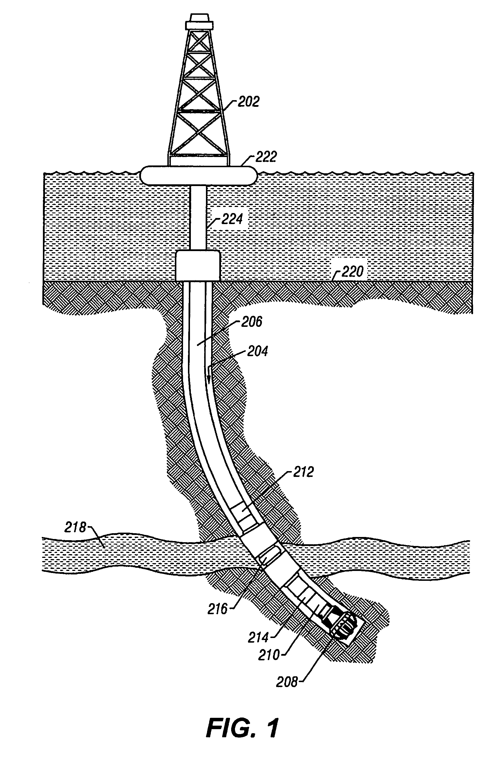
[0029]FIG. 1 illustrates an embodiment of the present invention deployed in a borehole. The present invention is suitable for deployment in either a wire line, slick line or monitoring while drilling environment. FIG. 1 illustrates a preferred embodiment of the present invention deployed in a monitoring while drilling operation.

[0030]Turning now to FIG. 1, FIG. 1 is a drilling apparatus according to one embodiment of the present invention. A typical drilling rig 202 with a borehole 204 extending there from is illustrated, as is well understood by those of ordinary skill in the art. The drilling rig 202 has a work string 206, which in the embodiment shown is a drill string. The drill string 206 has attached thereto a drill bit 208 for drilling the borehole 204. The present invention is also useful in other types of work strings, and it is useful with a wireline, jointed tubing, coiled tubing, or other small diameter work string such as snubbing pipe. The drilling rig 202 is shown pos...


PUM

PropertyMeasurementUnit
FWHMaaaaaaaaaa
path lengthaaaaaaaaaa
wavelengthaaaaaaaaaa

Abstract

The present invention provides a simple, robust, and versatile high-resolution spectrometer that is suitable for downhole use. The present invention provides a method and apparatus incorporating a spinning, oscillating or stepping optical interference filter to change the angle at which light passes through the filters after passing through a sample under analysis downhole. As each filter is tilted, the color or wavelength of light passed by the filter changes. Black plates are placed between the filters to isolate each filter's photodiode. The spectrometer of the present invention is suitable for use with a wire line formation tester, such as the Baker Atlas Reservation Characterization Instrument to provide supplemental analysis and monitoring of sample clean up. The present invention is also suitable for deployment in a monitoring while drilling environment. The present invention provides a high resolution spectometer which enables quantification of a crude oil's percentage of aromatics, olefins, and saturates to estimate a sample's gas oil ratio (GOR). Gases such as CO2 are also detectable. The percentage of oil-based mud filtrate contamination in a crude oil sample can be estimated with the present invention by using a suitable training set and chemometrics, a neural network, or other type of correlation method.

Description

CROSS-REFERENCE TO RELATED APPLICATIONS[0001]This application is a continuation in part patent application of U.S. patent application Ser. No. 10 / 162,023 entitled A Method and Apparatus for a High Resolution Downhole Spectrometer by R. DiFoggio et al., filed on Jun. 4, 2002 now abandoned. This patent application is related to U.S. patent application Ser. No. 10 / 453,717, entitled “A Method and Apparatus for a Downhole Flourescence Spectrometer” by Rocco DiFoggio, Paul Bergen and Arnold Walkow, filed on Jun. 3, 2003 which is hereby incorporated herein by reference in its entirety. This application is related to U.S. patent application Ser. No. 10 / 162,030, entitled “A Method and Apparatus for a Derivative Spectrometer” by Rocco DiFoggio, Paul Bergen and Arnold Walkow, filed on Jun. 4, 2002 which is hereby incorporated herein by reference in its entirety. This application is related to the U.S. patent application Ser. No. 10 / 119,492 filed on Apr. 10, 2002 by Rocco DiFoggio et al., entit...

Claims


Application Information

Patent Timeline
Patent Type & Authority Patents(United States)
IPC IPC(8): G01J3/51E21B47/10G01J3/06G01J3/12G01J3/26G01J3/433G01N21/25G01N21/31
CPCE21B47/102G01J3/06G01J3/12G01J3/433G01N21/31G01J3/26G01J3/0202G01J3/0262G01J3/0291G01N2021/317G01J2003/1243G01N2021/3133G01N2021/3137E21B47/113
Inventor DIFOGGIO, ROCCOWALKOW, ARNOLDBERGREN, PAUL
Owner BAKER HUGHES INC
Why Eureka
Try Eureka