Magnet wheel of an internal combustion engine

a technology of internal combustion engine and magnet wheel, which is applied in the direction of machines/engines, mechanical energy handling, mechanical apparatus, etc., can solve the problem of low overall weight, and achieve the effect of uniform voltage supply, low cost, and rapid response of ignition electronics

Inactive Publication Date: 2007-10-16
ANDREAS STIHL AG & CO KG
View PDF12 Cites 24 Cited by
  • Summary
  • Abstract
  • Description
  • Claims
  • Application Information

AI Technical Summary

Benefits of technology

[0009]A magnet wheel is proposed whose magnet carrier is configured as a sheet metal packet of lamella-like layered sheet metal pieces. The sheet metal packet is layered modular-like from at least two differently configured profiled sheet-metal piece types. At least one profiled sheet-metal piece type is configured as an arm sheet-metal part having a hub section as part of the hub as well as being configured with an arm section which extends from the hub section radially outwardly up to the region of the magnet carrier. At least one further profiled sheet-metal piece type is configured as a centrifugal mass sheet-metal piece lying essentially radially outside in the peripheral region of the magnet carrier. With the modular-like configuration of the sheet metal packet of various standardized profiled sheet-metal piece types, a variable adaptation of the mass characteristics of the magnet wheel to the particular requirements can be achieved with simple means. A portion of the sheet metal packet is formed by the arm sheet-metal parts into which the hub section is integrated. A separate hub is then unnecessary whereby the configuration of the magnet wheel is simplified. The additional centrifugal mass sheet-metal pieces are concentrated with their respective masses at a large radius relative to the rotational axis whereby a high inertial torque results with low overall weight. The arm sections reach inwardly up to the hub region with only a slight mass component close to the hub. The additional centrifugal mass sheet-metal pieces improve the ratio of rotational mass inertia to total weight. The modular-like configuration permits an adaptation, for example to various work apparatus, by selecting from standardized profiled sheet-metal piece types and modular-like adapted layer configurations.
[0013]In an advantageous embodiment, a spoked-wheel sheet-metal part is provided wherein the first profiled sheet-metal piece type of the arm sheet-metal part and the second profiled sheet-metal piece type of the annular sheet-metal part are joined as one piece. The advantages of the arm sheet-metal part and that of the annular sheet-metal part are effectively combined. Building upon the spoked-wheel sheet-metal part, a modular-like layered sheet metal packet can be formed wherein additional annular sheet-metal pieces lie compactly against the annular region of the spoked-wheel sheet-metal parts. The additional annular sheet-metal pieces form an effective inertial mass while the arm regions are configured only in a portion of the sheet-metal packet. The component of the sheet-metal parts with corresponding arm regions can be selected so small that the required mechanical characteristics are given and without an excessive mass component coming to lie close to the rotational axis.
[0014]In a practical embodiment, the sheet-metal packet comprises a further profiled sheet-metal piece type in the form of a hub annular disc. At least one hub annular disc is mounted radially inwardly as part of the hub. For only a slight number of arm sheet-metal pieces having hub sections, the hub region can be thickened by the hub annular discs with only a slight increase in mass. There results a high carrying capacity of the hub which is adaptable in a modular manner by selecting a corresponding number of hub annular discs.
[0018]A form material is advantageously cast about the magnet carrier. There results a shielding of the sheet-metal packet against external influences such as contamination, corrosion or the like. Light metal castings of aluminum, magnesium or the like can be used as form materials. It is practical to select an injection-molded plastic as a form material. The processing temperature of the plastic lies below the Curie temperature of the permanent magnets. The permanent magnets can be inserted into the magnet holder premagnetized in advance of coating. A subsequent magnetization after coating is not required. A loss of the premagnetization because of the effect of heat of the injection molding operation is not a problem.
[0019]In an advantageous further embodiment of the invention, a fan wheel for generating a cooling air flow for the engine is formed by the forming material. The form material thereby exercises multiple functions as a holding means for the sheet metal pieces, as a protective casement as well as a fan wheel. An integral component with a low number of parts and reduced manufacturing complexity is formed.

Problems solved by technology

The additional centrifugal mass sheet-metal pieces are concentrated with their respective masses at a large radius relative to the rotational axis whereby a high inertial torque results with low overall weight.

Method used


Image

  • Magnet wheel of an internal combustion engine
  • Magnet wheel of an internal combustion engine
  • Magnet wheel of an internal combustion engine

Examples


Embodiment Construction

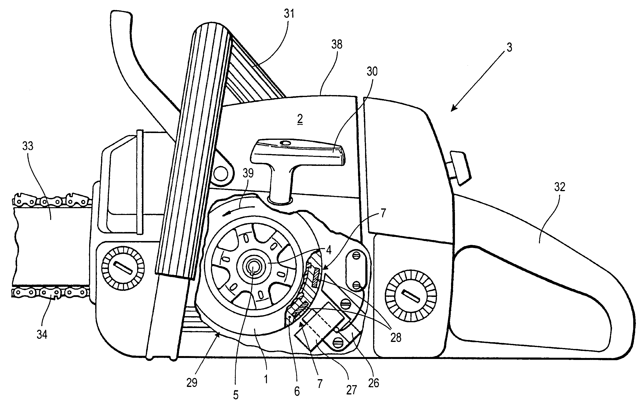
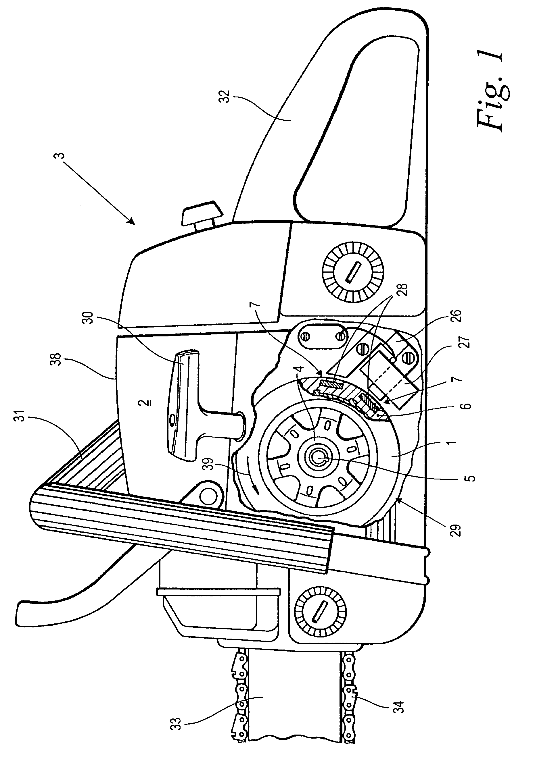
[0035]FIG. 1 shows a work apparatus 3 in the form of a motor-driven chain saw by way of example. The work apparatus 3 could also be a suction / blower apparatus, a brushcutter or another comparable portable handheld work apparatus.

[0036]The work apparatus 3 includes a housing 38 having a forward handle 31 and a rearward handle 32 for carrying and guiding the work apparatus. A guide bar 33, on which a saw chain 34 runs, is shown in the forward region of the work apparatus 3 with only a segment of the guide bar shown. The saw chain 34 is driven by a drive motor 2 (not shown) in the housing 38. The drive motor is configured as a single-cylinder two-stroke internal combustion engine.

[0037]The drive motor 2 includes a rotatingly driven crankshaft 5 on which a magnet wheel 1 is attached. The magnet wheel 1 includes a hub 4 with which it is attached to the crankshaft 5 so as to rotate therewith. Part of the magnet wheel 1 is a magnet carrier wherein an arrangement of magnets 28 is held by me...


PUM


Abstract

A magnet wheel (1) for an internal combustion engine, especially a drive motor (2) for a portable handheld work apparatus includes a hub (4) for fixing to a crankshaft (5) of the drive motor (2) and a magnet carrier (6) having at least one magnet holder (7) provided peripherally on the magnet wheel (1). The magnet carrier (6) is a sheet-metal packet (9) of lamella-like layered plates (8). The sheet-metal packet (9) is layered modular-like from at least two differently configured profiled sheet-metal piece types (10, 11, 12). At least one profiled sheet-metal piece type (10) is configured as an arm plate (13) with a hub section (14) as part of the hub (4) as well as an arm section (15) which extends from the hub section (14) radially outwardly up to the region of the magnet carrier (6). At least one additional profiled sheet-metal piece type (11) is configured as a centrifugal mass sheet-metal piece (16) which lies essentially radially outwardly in the peripheral region of the magnet carrier (6).

Description

CROSS REFERENCE TO RELATED APPLICATION[0001]This application claims priority of German patent application no. 10 2004 036 548.2, filed Jul. 28, 2004, the entire content of which is incorporated herein by reference.FIELD OF THE INVENTION[0002]The invention relates to a magnet wheel of an internal combustion engine including that of a drive motor for a portable handheld work apparatus.BACKGROUND OF THE INVENTION[0003]In handheld work apparatus such as saw chains, blower / suction apparatus, brushcutters or the like having an internal combustion engine as a drive motor, a magnet wheel is attached to the crankshaft of the drive motor. The magnet wheel includes a magnet carrier of iron wherein at least one magnet is held by means of a magnet holder. The magnet wheel rotates during operation of the engine and the permanent magnet, which is held in the magnet wheel, is guided past an armature having a coil. The armature is fixed to the housing. A voltage is induced in the coil which is used ...

Claims


Application Information

Patent Timeline
Patent Type & Authority Patents(United States)
IPC IPC(8): F02P1/02
CPCH02K7/02H02K21/14Y02E60/16
Inventor LEUFEN, HEINRICHWIDMANN, RAINERHUSGES, MARKUS
Owner ANDREAS STIHL AG & CO KG
Why Eureka
Try Eureka