Precision sensor for a hydraulic cylinder

a technology of precision sensor and hydraulic cylinder, which is applied in the field of position sensor, can solve the problems of requiring great skill, improper operation equipment poses a safety hazard, and operators have been known to damage overhead utility wires, underground wiring, underground gas lines, etc., and achieves the effect of reducing construction costs, convenient formation, and convenient operation

Inactive Publication Date: 2007-11-06
CONTROL PRODS
View PDF78 Cites 45 Cited by
  • Summary
  • Abstract
  • Description
  • Claims
  • Application Information

AI Technical Summary

Benefits of technology

[0012]As a further feature of a sensor according to the principles of the invention, and as a still further exemplary embodiment thereof, there is provided a construction of the sensor frame by the use of a plurality of stamped plates that are contained within the hydraulic cylinder, preferably about five of such stamped plates and which stamped plates facilitate the ease and therefore reduce the cost of the constructing of an exemplary sensor, that is, with the use of a plurality of stamped plates, a frame for the sensor can be readily formed by the stamping process and which eliminates the need for specially complex machined blocks to thus reduce the cost of such construction. Also, with such embodiment, in addition to the considerable cost savings, there is a greater flexibility in the production of sensor frames of differing sizes by merely adapting the stamping techniques to produce the stamped plates of the appropriate dimensions for the particular desired size of sensor. As such, with relatively minimal tooling changes, the size of the various sensor frames can be changed, modified and adapted to accommodate a wide variety of dimensioned sensors to be located within the hydraulic cylinder.
[0014]In order to pass the electrical conductors through the wall of the hydraulic cylinder, there is a high pressure seal assembly that provides an electrical path for the sensor that is located within the high pressure environment of the cylinder to an external connector that is in the ambient environment so that some external electronic equipment can recognize the various signals from the sensor and interpret those signals to determine the position of the piston. The high pressure seal assembly therefore comprises a thermoplastic connector that cooperates with one of the aforedescribed hollow port inserts and which has a plurality of solid conductive pins that extend from a connector within the cylinder to an external connection in the outer environment. The pins are sealed within the plastic material of the connector and may be affixed therein by ultrasonic swaging or insert molding to insure a good seal along the solid conductive pins to prevent leakage from the high-pressure environment. The external peripheral surface of the connector can be sealed within the opening in the wall of the cylinder by means such as an O-ring. The eventual seal is relatively low cost and yet has the pressure resistance necessary for the application. As an advantage, the high pressure seal assembly according to the principles of the invention allows the use of the standard hydraulic fluid port already present in commercial hydraulic cylinders, and provides an inexpensive easily facilitated means of forming an electrical path from a high pressure environment to a environment normally at ambient atmospheric pressure.
[0015]As a still further feature, and which may be optional, there are provided piston stops within the hydraulic cylinder in order to protect the sensor. Since the sensor of this invention is preferably located within the hydraulic cylinder, it is possible during the normal operation of the hydraulic cylinder for the piston to be fully retracted and, in such case, the piston could encounter the sensor and crush that sensor. The piston stops are therefore incorporated as components of the construction of the sensor and its mounting means, such that the sensor can be safely located within the hydraulic cylinder at the back end thereof and which prevents the piston from contacting and potentially damaging the sensor. The piston stops can be constructed of a metal stamping and are formed to have an arcuate configuration to fit in a complementary relationship with the interior of the hydraulic cylinder. By the use of the piston stops, standard hydraulic cylinders can be used and the sensor is protected and wherein there is no need for the manufacturer of the hydraulic cylinders to build in costly stops or bumpers in the manufacturing of the cylinders themselves.

Problems solved by technology

The use of levers to control hydraulic equipment depends upon manual dexterity and requires great skill.
Improperly operated equipment poses a safety hazard, and operators have been known to damage overhead utility wires, underground wiring, water mains, and underground gas lines through faulty operation of excavators, bucket loaders or like equipment.
An inexperienced or unskilled operator typically fails to achieve the optimum performance levels of the equipment.
For instance, the operator may not consistently apply the force necessary for peak performance due to a concern over striking a hazard.
Efficiency is also compromised when the operator fails to drive a cylinder smoothly.
The operator alternately overdrives or underdrives the cylinder, resulting in abrupt starts and stops of the moveable element and thereby derating system performance.
As a result, the skill level necessary to properly and safely operate heavy equipment is typically imparted through long and costly training courses and apprenticeships.
It is a disadvantage of these sensors that they mount to the outside of the machinery, thereby exposing them to the environment.
In the case of heavy equipment, this environment includes severe temperatures, excessive moisture, and air-borne particulate matter which may infect the sensor.
In the case of optical, conductive plastic and metal-in-glass technologies, the sensors would rapidly degrade if used on construction equipment.
Furthermore, some of these sensors use contacting components that are susceptible to wear, vibration and temperature.
As a result, no sensor mountable to the outside of heavy equipment or relying upon contacting elements has gained widespread use in the industry.
These systems, however, have not replaced the less expensive potentiometers due to their complexity of use and their expense.
Despite the development of highly sophisticated control systems, computer processors and application specific software, the implementation of this technology in electrohydraulic equipment has been curtailed by the failure to provide a long-life, cost-effective precision sensor operable in harsh environments.

Method used


Image

  • Precision sensor for a hydraulic cylinder
  • Precision sensor for a hydraulic cylinder
  • Precision sensor for a hydraulic cylinder

Examples


Embodiment Construction

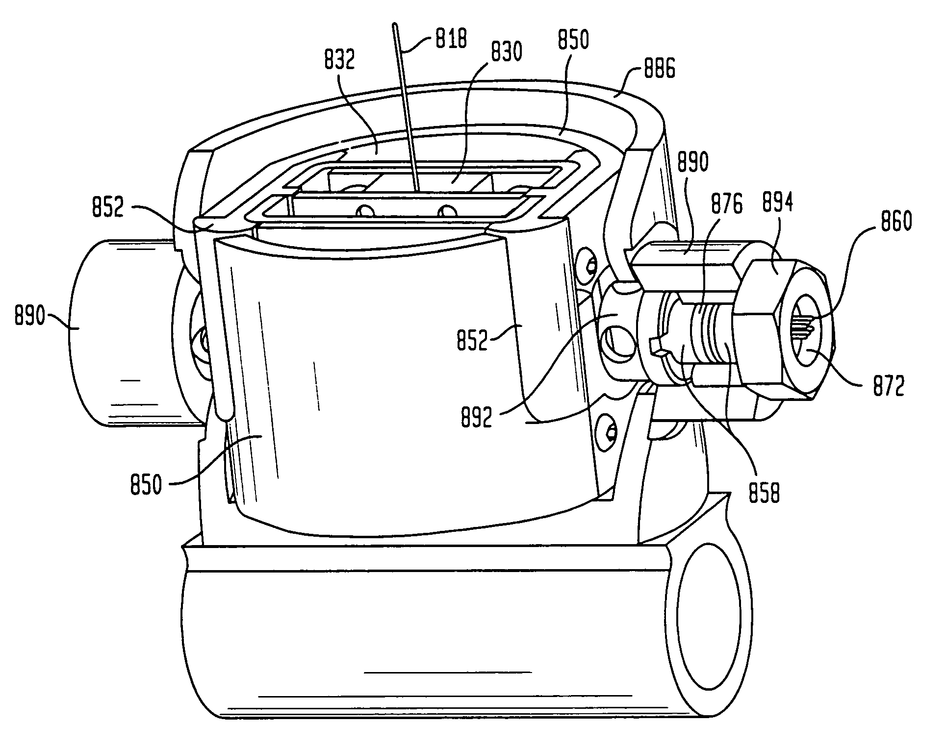
[0033]A feedback sensor for a cylinder according to the principles of the invention provides a precision signal indicative of a piston position with relation to a cylinder. The sensor is durable, maintains a long life and is configured for use in harsh environments. An exemplary sensor mounts inside a hydraulic cylinder, thereby protecting the sensor, and uses a non-contacting transducer to provide the precision signal. A converting element converts the motion of the piston to a proportional motion of a translating member. The transducer, which can be located remotely from the piston, senses the position of the translating member, and provides an electrical output signal indicating the piston's position. This signal can be conditioned and used in a feedback control system, a user interface or any system where such a signal is desirable.

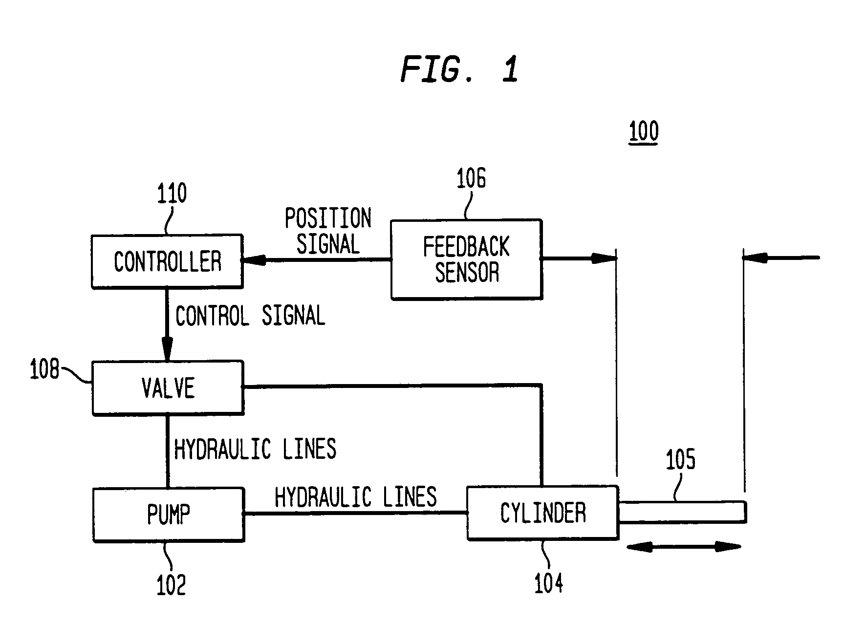
[0034]In FIG. 1, a block diagram of an exemplary feedback control system 100 is shown. The control system 100 comprises a hydraulic cylinder 104 actu...


PUM


Abstract

A sensor mountable within a hydraulic cylinder provides a precision signal indicative of the position of the piston. The sensor includes a flexible connector attached between the cylinder piston and a converting element for sensing the piston displacement. The converting element comprises a pick-up spool, under tension, coupled to the other end of the connector and rotatable about an axis. A lead screw engages threads on the spool, and translates linearly when the spool rotates. A non-contacting electromechanical transducer senses the position of the lead screw, and provides an output signal proportional to the motion or position of the movable element. The transducer may be an LVDT or other transducer. A high-pressure seal assembly provides an electrical path between the sensor and an external connector. A piston stop prevents the piston from damaging the sensor. The sensor is held within the cylinder by port inserts threaded into standard cylinder hydraulic fluid ports and advanced inwardly to grip the sensor.

Description

RELATED APPLICATIONS[0001]This application is a continuation of nonprovisional patent application Ser. No. 09 / 793,218, filed Feb. 26, 2001 now U.S. Pat. No. 6,694,861 entitled “PRECISION SENSOR FOR A HYDRAULIC CYLINDER” which, in turn, is a continuation-in-part of and claims the benefit of U.S. application Ser. No. 09 / 302,701, now U.S. Pat. No. 6,234,061, filed on Apr. 30, 1999, entitled “PRECISION SENSOR FOR A HYDRAULIC CYLINDER” which, in turn, claims the benefit of U.S. Provisional Application 60 / 104,886 filed on Oct. 20, 1998.FIELD OF THE INVENTION[0002]The invention generally relates to position sensors, and more particularly, to linear position sensors for use on power cylinders.BACKGROUND[0003]Equipment implementing hydraulic cylinders for mechanical movement, such as excavators and other heavy construction equipment, depend upon operators to manually control the moveable elements of the equipment. The operator must manually move control levers to open and close hydraulic val...

Claims


Application Information

Patent Timeline
Patent Type & Authority Patents(United States)
IPC IPC(8): F01B25/04
CPCF15B15/283
Inventor GLASSON, RICHARD O.
Owner CONTROL PRODS
Why Eureka
Try Eureka