Method and arrangement for changing the spectral composition and/or intensity of illumination light and/or specimen light in an adjustable manner

a specimen light and spectral composition technology, applied in the field of microscopy, can solve the problems of not being able to adjust in a flexible manner, limiting the efficiency of typically 70% to 90%, and separating excitation light from specimen light in a wavelength-dependent manner, so as to reduce the sensitivity of detection, increase the noise of the detector, and increase the effect of amplification

Inactive Publication Date: 2007-11-20
CARL ZEISS MICROSCOPY GMBH
View PDF12 Cites 5 Cited by
  • Summary
  • Abstract
  • Description
  • Claims
  • Application Information

AI Technical Summary

Benefits of technology

[0036]The quantity of dye signatures that may be used simultaneously, i.e., the quantity of characteristics, for example, of cells that can be investigated simultaneously, can be increased by means of the methods according to the invention. When the spectral signatures of the individual dyes overlap extensively or are very close to one another, the detected wavelength range or numerical aperture must be limited, according to the prior art, for separate detection of the fluorescence signals of individual dyes. This reduces the sensitivity of detection, i.e., increases the noise of the detectors, because greater amplification must be used. This is avoided by the methods and arrangements according to the invention.

Problems solved by technology

In all of the methods according to the prior art, it is disadvantageous that the separation of the excitation light from the light emitted by the specimen is carried out in a wavelength-dependent manner, i.e., can not be adjusted in a flexible manner, or with a limited efficiency of typically 70% to 90%, depending on the required spectral characteristics and the quantity of illumination lines.

Method used


Image

  • Method and arrangement for changing the spectral composition and/or intensity of illumination light and/or specimen light in an adjustable manner
  • Method and arrangement for changing the spectral composition and/or intensity of illumination light and/or specimen light in an adjustable manner
  • Method and arrangement for changing the spectral composition and/or intensity of illumination light and/or specimen light in an adjustable manner

Examples


Embodiment Construction

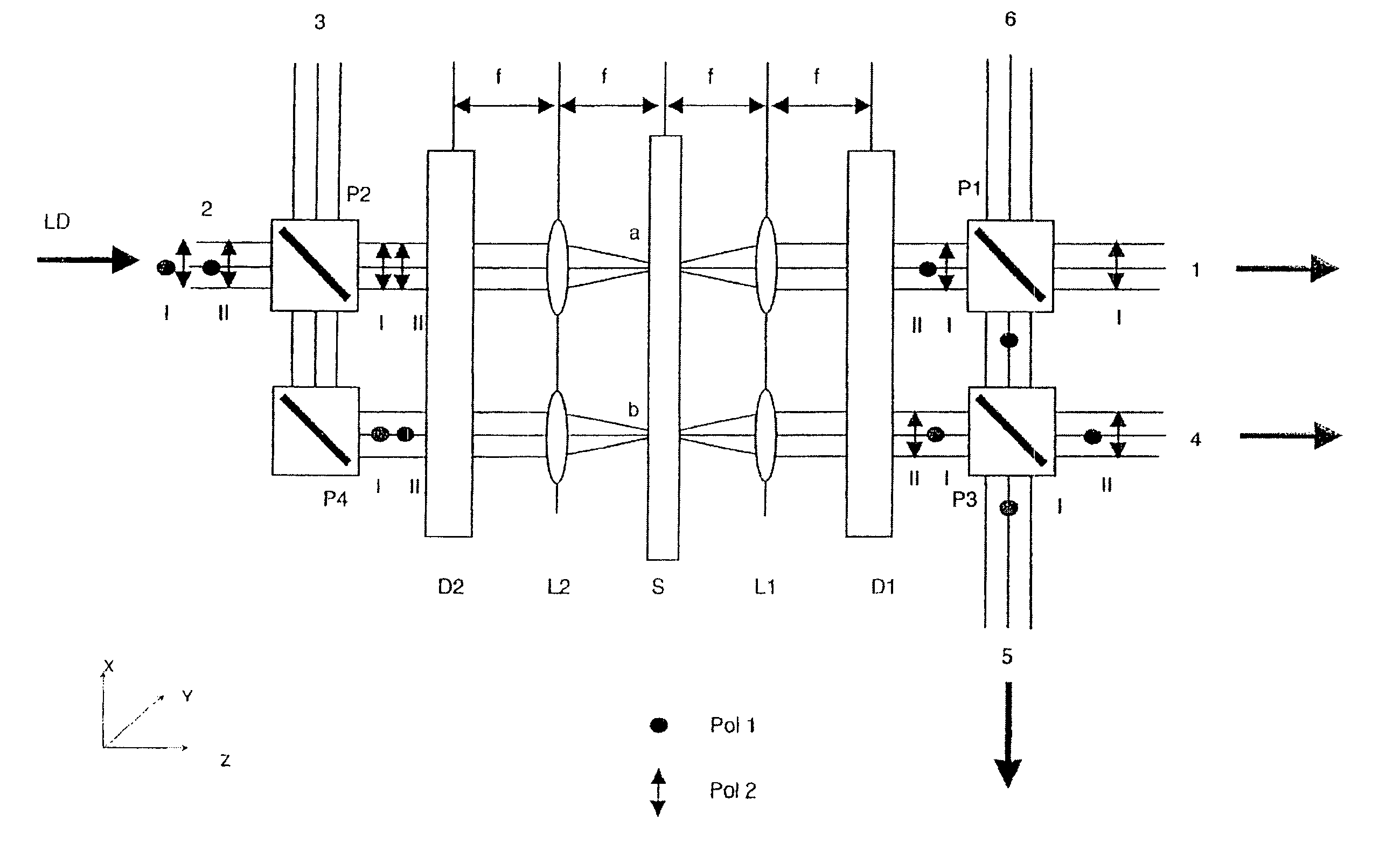
[0051]Various arrangements by which the light radiation (hereinafter, detection light) excited and / or backscattered in the specimen can be separated from the excitation light in a particularly efficient manner will be described more fully in the following. The arrangements are accordingly suitable in particular for fast multitracking with a flexible separation of the excitation radiation from the detection light that is adapted with respect to spectrum. In the following context, light that is emitted by the specimen is light which is preferably radiated from the specimen in a large solid angle. This light is not polarized (unpolarized). This refers in particular to fluorescent light and luminescent light excited in the specimen and backscattered light.

1. Principle of operation of the arrangement for variable separation of excitation light from detection light

[0052]The construction of the arrangement for separating the excitation light from the detection light is shown schematically ...


PUM

PropertyMeasurementUnit
edge lengthaaaaaaaaaa
wavelengthaaaaaaaaaa
anglesaaaaaaaaaa

Abstract

Method and arrangement for changing the spectral composition and/or intensity of illumination light and/or specimen light in an adjustable manner, wherein a spatial separation into radiation components of different polarization is carried out with a first polarizing device, a spectral, spatial splitting of at least one radiation component is carried out with first dispersion device, the polarization state of at least one part of the spectrally spatially split radiation component is changed, and a spatial separation and/or combination of radiation components of different polarization are/is carried out by a second polarizing device, wherein a spatial combination of radiation components which are changed and not changed with respect to their polarization state is advantageously carried out by a second dispersion device.

Description

CROSS-REFERENCE TO RELATED APPLICATION[0001]This application claims priority of German Application No. 102 41 472.6, filed Sep. 4, 2002, the complete disclosure of which is hereby incorporated by reference.BACKGROUND OF THE INVENTION[0002]a) Field of the Invention[0003]The invention is directed to a method in microscopy, particularly fluorescence microscopy, laser scanning microscopy, fluorescence correlation microscopy and scanning nearfield microscopy, for examining primarily biological specimens, preparations and associated components. This includes methods for screening active ingredients (high throughput screening) based on fluorescence detection. Simultaneous examinations of specimens with multiple fluorophores in real time by means of simultaneous illumination of the specimen at a plurality of points on the specimen are therefore possible with overlapping fluorescence spectra even in three-dimensional structures of thick specimens.[0004]b) Description of the Prior Art[0005]A ...

Claims


Application Information

Patent Timeline
Patent Type & Authority Patents(United States)
IPC IPC(8): G02B21/06G01J3/44G01N21/64G01J3/447G01N15/00G01N15/14G02B21/00
CPCG01J3/02G02B21/002G01J3/0229G01J3/10G01J3/4406G01N15/1434G01N21/6445G01N21/6458G01J3/0224G01J3/447G01J2003/1282G01J2003/1286G01N2015/0065G01N2015/149G01N2015/1493
Inventor WOLLESCHENSKY, RALF
Owner CARL ZEISS MICROSCOPY GMBH
Why Eureka
Try Eureka