
Method and apparatus for data processing

Inactive Publication Date: 2007-12-04
APPLE INC
View PDF30 Cites 73 Cited by
  • Summary
  • Abstract
  • Description
  • Claims
  • Application Information

AI Technical Summary

Problems solved by technology

The small amount of logic combined with continuing advancement in silicon technology, results in the significant portion of that area being unused.
This arrangement may require the data to be transferred between the host system and the media processor, thus it may impact performance.
This results in code expansion and therefore in memory, bandwidth, and instruction cache related inefficiencies.
However, the emergence of high-bandwidth applications, such as three-dimensional (3-D) graphics applications, threatens to overload the PCI bus.
However, since the AGP address ranges are designed dedicated to the AGP accelerator, it is a fixed memory range that may not be shared with other components in the system.
In addition, the media processor in an AGP system normally uses mapped non-coherent memory access.
Lack of coherent access of the conventional approaches posts an inconvenience to the applications.
While this approach can be used to perform table look-up for a vector of data from a single small look-up table, there are severe limitations in its practical applications in processing large look-up tables.
Further, due to the limited size of a vector register file, only a part of look-up table entries may be loaded into the vector register file when large look-up tables are used.
Thus, it can be a very inefficient operation.
However, such functionality is very limited; and such hardware cannot be used to perform general purpose table look-up for a vector of data elements from an array of look-up tables.
However, two sequential look-up operations, as well as associated overhead for preprocessing, are necessary to decode a code word.
The software implementations of matrix transposition are computationally expensive.
However, the device described in U.S. Pat. No. 6,021,420 is specialized for matrix transposition and is difficult to be adapted for other applications.
However, since dedicated hardware is required to perform color space conversion according to U.S. Pat. No. 5,510,852, such an approach is generally costly and is difficult to adapt to different configurations.
Compression / decompression of video data is an expensive operation.
Since such add-in-boards are quite expensive, video editing so far has been in the domain for video professionals.
Consumer video editing software applications implemented on general purpose processors are slow and suffer from poor quality due to massive computation requirements.
The drawbacks of the hardware implementations using dedicated chipsets are the high cost, lack of scalability, and lack of compatibility with other components in video systems.
The drawback of the software decoders on the general purpose CPUs is that the performance of a decoder highly depends on the computing environment, such as the run time usages of the CPU, memory, cache, and I / O devices.
The instruction sets of general purpose processors are not well suited for processing encoded bit streams.
Variable Length Decoding (VLD), when implemented on a general purpose processor, is limited in performance by the operations for table look-up and conditional branch.
A single look-up table approach is highly inefficient from caching point of view.
The cache miss penalty can dramatically reduce the performance.
Multi-table approaches reduce the amount of memory required by the look-up table by looking-up sequentially in a number of smaller look-up tables, and thus suffers from increased execution time due to multiple sequential look-up operations and associated overheads.
Further, with High Definition TV (HDTV), the amount of processing power required for decompression can be very high.

Method used


Image

  • Method and apparatus for data processing
  • Method and apparatus for data processing
  • Method and apparatus for data processing

Examples


Embodiment Construction

[0159]The following description and drawings are illustrative of the invention and are not to be construed as limiting the invention. Numerous specific details are described to provide a thorough understanding of the present invention. However, in certain instances, well known or conventional details are not described in order to not unnecessarily obscure the present invention in detail.

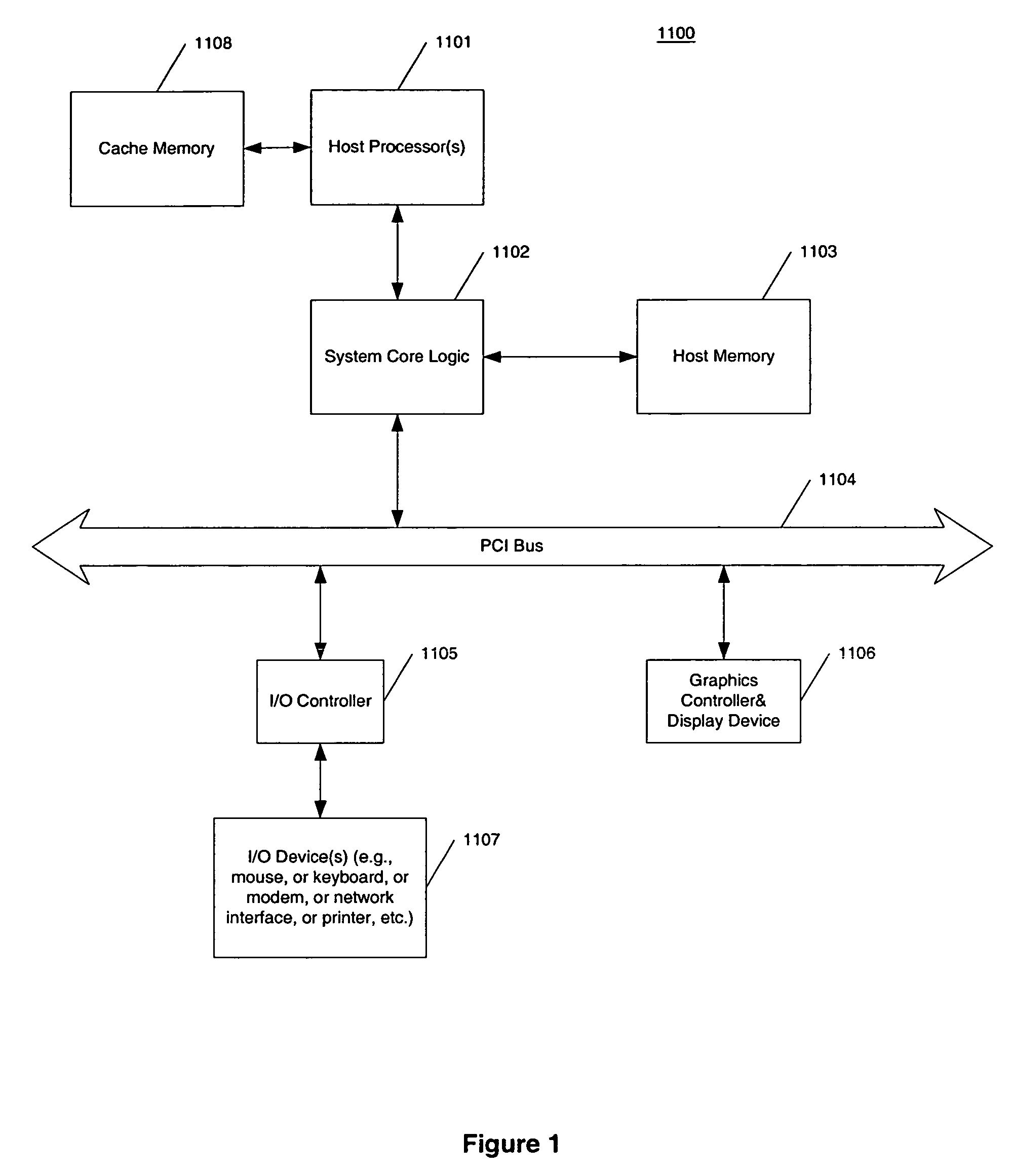
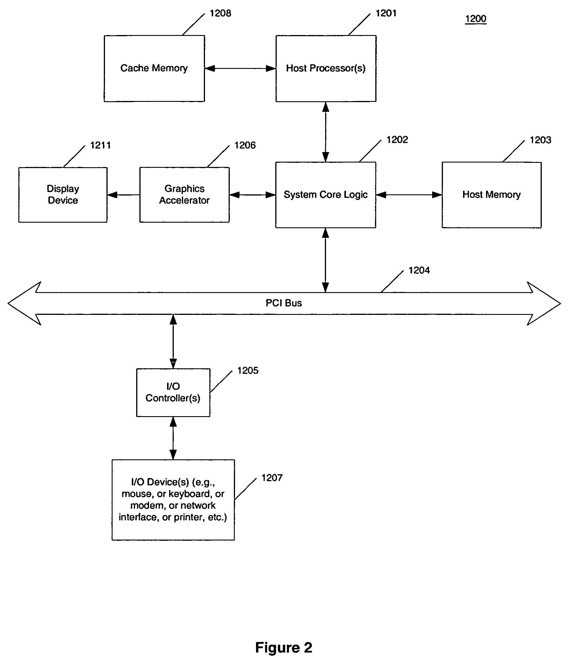
[0160]FIG. 1 shows an example of a typical computer system, which may be used with the present invention. Note that while FIG. 1 illustrates various components of a computer system, it is not intended to represent any particular architecture or manner of interconnecting the components as such details are not germane to the present invention. It will also be appreciated that network computers and other data processing systems which have fewer components or perhaps more components may also be used with the present invention. The computer system of FIG. 1 may, for example, be an Apple Macintosh computer...


PUM


Abstract

Methods and apparatuses for a data processing system are described herein. In one aspect of the invention, an exemplary apparatus includes a chip interconnect, a memory controller for controlling the host memory comprising DRAM memory, the memory controller coupled to the chip interconnect, a scalar processing unit coupled the chip interconnect wherein the scalar processing unit is capable of executing instructions to perform scalar data processing, a vector processing unit coupled the chip interconnect wherein the vector processing unit is capable of executing instructions to perform vector data processing, and an input / output (I / O) interface coupled to the chip interconnect wherein the I / O interface receives / transmits data from / to the scalar and / or vector processing units.

Description

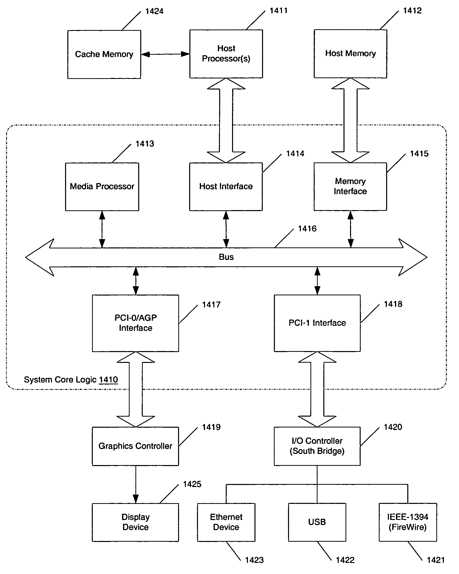
FIELD OF THE INVENTION[0001]The invention relates to the general field of data processors. In particular, it relates to methods and apparatuses for functional units of the data processors.BACKGROUND OF THE INVENTION[0002]FIG. 3 shows a typical computer system having at least one host processor 1301 and host memory 1302. The system core logic chip 1300, also known as a memory controller or a north bridge, facilitates data transfer between the host memory 1302 through a memory interface 1304, the host processor 1301 through a host interface 1303, graphics controller 1308 through a PCI-0 / AGP interface 1306 and other peripherals such as input / output (I / O) controller 1309 through PCI-1 interface 1307. An IEEE-1394 bus 1310, also known as a FireWire bus, may be coupled to the I / O controller 1309. The FireWire bus 1310, in some applications, may be directly coupled to the system core logic chip 1300 through the PCI-1 interface 1307. The FireWire bus 1310 provides interfaces to other FireWi...

Claims


Application Information

Patent Timeline
IPC IPC(8): G06F15/76G06F15/17
CPCG06F9/30014G06F9/30032G06F9/30036G06F9/3004G06F9/30047G06F15/8053G06F9/3802G06F9/382G06F9/3853G06F9/3879G06F9/3885G06F9/30101
Inventor TRIVEDI, SUSHMA SHRIKANTBRATT, JOSEPH P.BENKUAL, JACKARNOLD, VAUGHN TODDIWAMOTO, DEREK FUJIO
Owner APPLE INC
Learn More