Optical fiber and method for making such fiber

a rare earth doped, optical fiber technology, applied in the direction of optical fibres with polarisation, active medium materials, instruments, etc., can solve the problems of low capability of high-power multi-mode optical sources, low thermal stability of plastics for many applications, and easy moisture damage, etc., to achieve long deployment life and high coupling efficiency

Active Publication Date: 2007-12-25
CORNING INC
View PDF10 Cites 240 Cited by
  • Summary
  • Abstract
  • Description
  • Claims
  • Application Information

AI Technical Summary

Benefits of technology

[0024]Some of the advantages the optical fibers disclosed herein are: high coupling efficiency, suitability for high optical power applications (100 Watts or higher), and suitability for use as polarization maintaining fiber and long deployment life.

Problems solved by technology

This type of fiber has low capability of handling high power multimode optical sources due to the difficulty of efficiently coupling multimode light from a high power optical (light) source (also referred to herein as optical pump or pump) into the rare-earth doped fiber core.
Such plastic may not have the desired thermal stability for many applications, may delaminate from the first cladding, and may be susceptible to moisture damage.
In addition, this type of double clad optical fiber may be suitable only for sustained use with relatively low power (lower than 20 Watts) optical sources.
When high power sources (more than 100 Watts) are utilized, this type of optical fiber heats and the polymer material of the outer cladding layer carbonizes or burns, resulting in device failure, especially when the fiber is bent.
At medium powers (20 Watts to below 100 Watts), the polymer outer cladding ages relatively quickly, losing its mechanical and optical characteristics and becoming brittle, thus shortening the device life.
The disclosed fiber, however, is not suitable for high power applications because it has a relatively low outer cladding diameter and NA, and therefore, low coupling efficiency due to light leakage outside of the optical fiber.
That is, a relatively large portion of the light does not enter the optical fiber and is lost.
Although this may not be an issue in applications when only a small amount of optical power needs to be coupled into the fiber, such fiber is not efficient for high power applications when the light source power is 100 Watts or more.

Method used


Image

  • Optical fiber and method for making such fiber
  • Optical fiber and method for making such fiber
  • Optical fiber and method for making such fiber

Examples


example 1

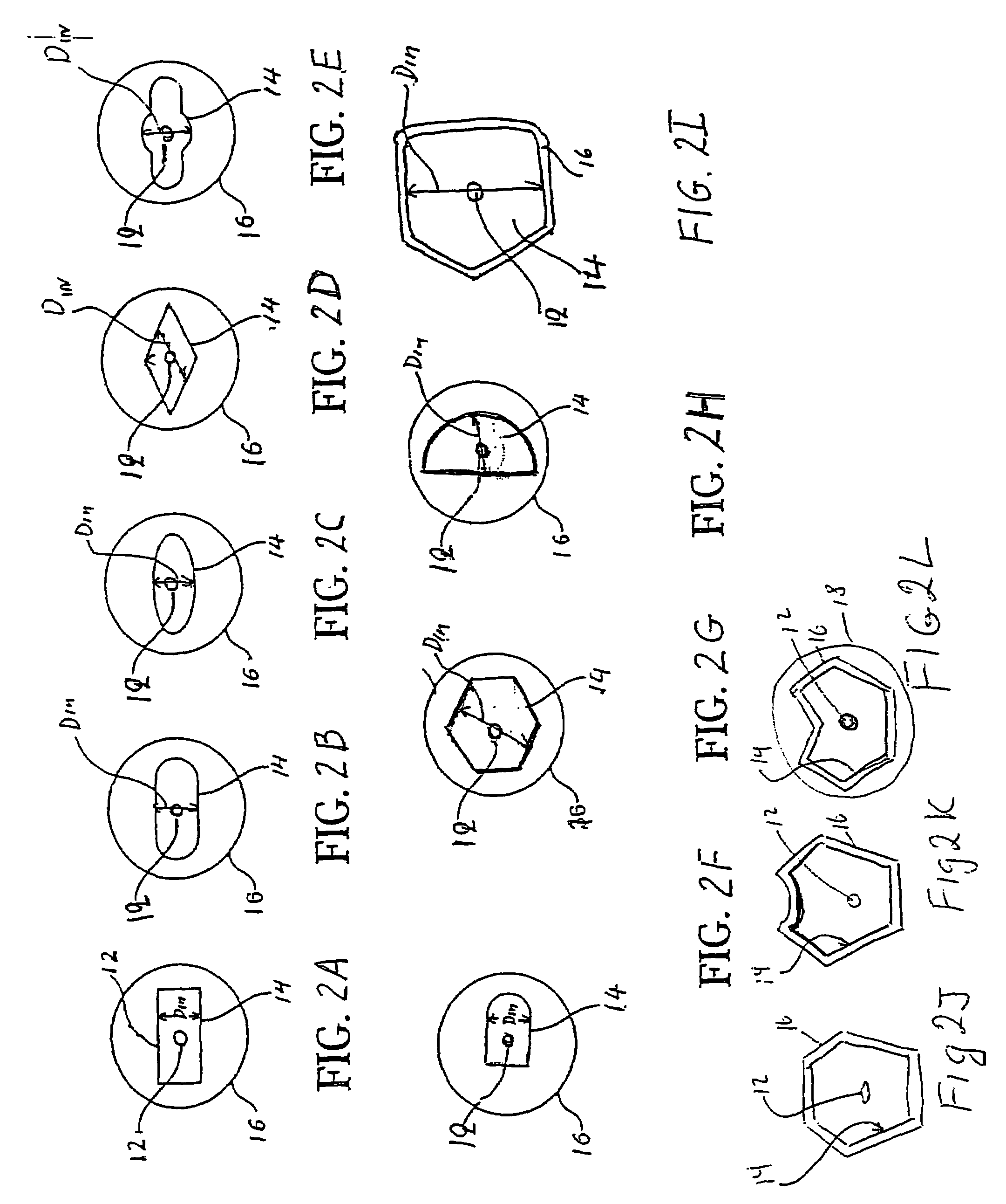
[0062]FIG. 4 illustrates a refractive index profile of a first exemplary optical fiber of the present invention. This optical fiber has the cross-section illustrated in FIG. 2I. The distance DIN between two opposing flat sides of this inner cladding crossection is 260 μm. FIG. 4 depicts this optical fiber's refractive index percent delta (relative to that of the pure silica) vs. the distance measured from the core center. The refractive index percent delta is defined herein as (n12−ns2) / 2ni2, where i=1, 2 or 3 and ns is the refractive index of pure silica. This optical fiber has a Yb doped core 12, a Ge-silica inner cladding (% delta ≈0.46) and an outer cladding 16 which doped with Fluorine and Boron. FIG. 4 shows that the relative refractive index difference (percent delta) of the core 12 is about 0.56, that the fluorine / boron doped outer cladding 16 has the refractive index percent delta of about −1.4. The Yb-doped fiber core is single-mode for the wavelengths above 1 μm. If the c...

example 2

[0083]FIG. 13 illustrates a refractive index profile of a second exemplary optical fiber of the present invention. More specifically, FIG. 13 depicts refractive index delta as vs. the radius for the second exemplary optical fiber. This optical fiber has a Yb doped, silica based core 12 which is multi mode at the lasing wavelength of 1100 μm, a silica based inner cladding 14 having two sections of almost the same index of refraction (delta %≈0) and an outer cladding 16 which is doped with fluorine. The NA of the inner cladding is 0.16. FIG. 13 illustrates that the refractive index difference (delta %) of the core 12 is about 0.7, that the fluorine doped outer cladding 16 has the refractive index delta of about −0.7. The core 12 and the first section of the inner cladding 14 are produced by an inside-vapor-deposition (IVD) process. The core Ge—Si soot is deposited inside the glass tube (first section of the inner cladding) and followed by solution Yb-doping of the core soot. The struc...

example 3

[0089]FIG. 16 illustrates a refractive index profile of a third exemplary optical fiber of the present invention. This optical fiber has a Yb doped core 12, a silica based, Ge doped inner cladding 14 with the relative refractive index (% delta %) of 0.3 and an outer cladding 16 which is doped with Fluorine. FIG. 16 shows that the refractive index difference (% delta) of the core 12 is about 0.7 and that the fluorine doped outer cladding 16 has the refractive index % delta of about −0.7. The specific composition for this optical fiber example is:[0090]Core 12: 0.8 wt % Yb2O3; 9.5 wt % P2O3; 5.4 wt % GeO2;[0091]Inner cladding 14: 6 wt % GeO2;[0092]Outer cladding 16: 2.3 wt % F


PUM

PropertyMeasurementUnit
weight percentaaaaaaaaaa
output powersaaaaaaaaaa

Abstract

According to one example of the invention an optical fiber comprises: (i) silica based, rare earth doped core having a first index of refraction n1; (ii) at least one silica based cladding surrounding the core and having a second index of refraction n2, such that n1>n2; wherein at least one of the core or cladding is doped with Al2O3, such that the ratio of max wt % to min wt % of Al2O3 concentration is less than 2:1.

Description

[0001]Parts of this invention were made with Government support under Agreement No. MDA972-02-3-004 awarded by DARPA. The Government may have certain rights in some of the claims of the invention.BACKGROUND OF THE INVENTION[0002]1. Field of the Invention[0003]The present invention relates generally to double clad rare earth doped optical fibers, and particularly to all glass rare earth doped optical fibers suitable for use with high power light sources or in optical fiber lasers and optical amplifiers.[0004]2. Technical Background[0005]Optical fiber has become a favorite medium for telecommunications due to its high capacity and immunity to electrical noise. Single clad rare earth doped optical fiber has been widely used in the field of optical amplifiers and fiber lasers. This type of fiber has low capability of handling high power multimode optical sources due to the difficulty of efficiently coupling multimode light from a high power optical (light) source (also referred to herei...

Claims


Application Information

Patent Timeline
Patent Type & Authority Patents(United States)
IPC IPC(8): G02B6/00C03B37/014C03B37/023C03C13/04G02B6/024G02B6/036H01S3/067H01S3/16
CPCC03B37/01413C03C13/046G02B6/0365G02B6/03694H01S3/06716C03B2207/90C03B2201/12C03B2201/14C03B2201/28C03B2201/31C03B2201/32C03B2201/34C03B2201/36C03B2203/04C03B2203/10C03B2203/23C03B2203/30G02B6/024G02B6/03611H01S3/1618C03B2207/85C03B2201/10
Inventor KIMBALL, RONALD L.KNOWLTON, ROBERT AMCCARTHY, JOSEPH EWANG, JIWALTON, DONNELL T.ZENTENO, LUIS A.
Owner CORNING INC
Why Eureka
Try Eureka