
Production of hydrocarbons

a technology of hydrocarbons and hydrocarbons, which is applied in the preparation of oxygen-containing compounds, organic chemistry, chemistry apparatus and processes, etc., can solve the problems of carbon monoxide formation on the exposed surface of catalysts, the occurrence of carbon monoxide on the exposed surface of tail gases of fischer-tropsch, and the reduction of the hydrogen to carbon oxide ratio

Inactive Publication Date: 2008-01-01
JOHNSON MATTHEY PLC
View PDF12 Cites 3 Cited by
  • Summary
  • Abstract
  • Description
  • Claims
  • Application Information

AI Technical Summary

Benefits of technology

[0009]We have found that operation at low overall steam ratios with economical reforming of the hydrocarbon feedstock may be achieved by dividing the feedstock into two streams, mixing the first stream with steam and feeding it to the primary reformer and feeding the second stream to the primary reformed gas before secondary reforming along with at least part of the tail gas from the Fischer-Tropsch process. The steam ratio is therefore lower overall but still sufficiently high in the primary reforming step to avoid carbon deposition.

Problems solved by technology

Thirdly the partial combustion effectively consumes some of the hydrogen present in the reformed gas, thus decreasing the hydrogen to carbon oxides ratio.
Fischer-Tropsch tail gas is liable to contain a significant amount of carbon monoxide.
Use of lower steam ratios, for example steam ratios below 1.00, can, however, lead to carbon formation on the exposed surfaces of the catalyst.
Such carbon formation has the undesirable effect of increasing the pressure drop through the catalyst.
It can also result in a loss of catalyst activity.

Method used


Image

  • Production of hydrocarbons
  • Production of hydrocarbons
  • Production of hydrocarbons

Examples


example 1

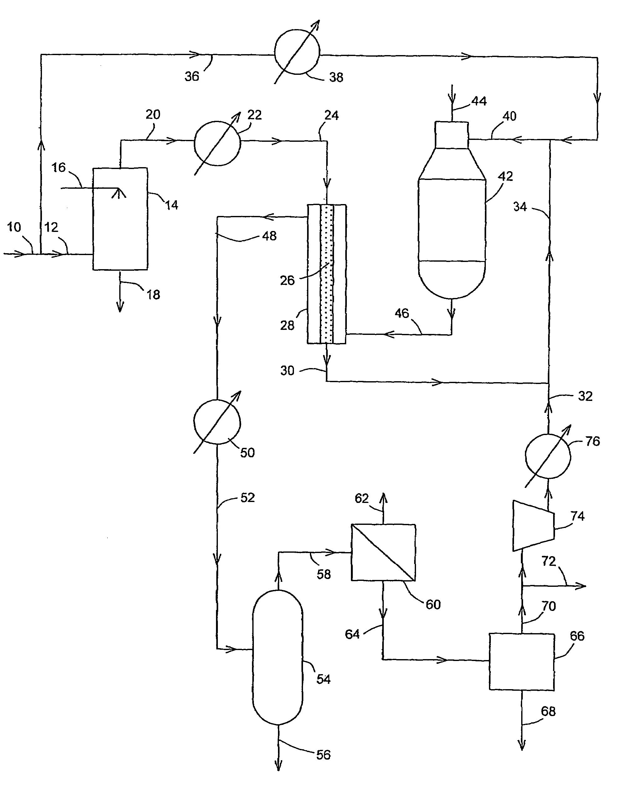
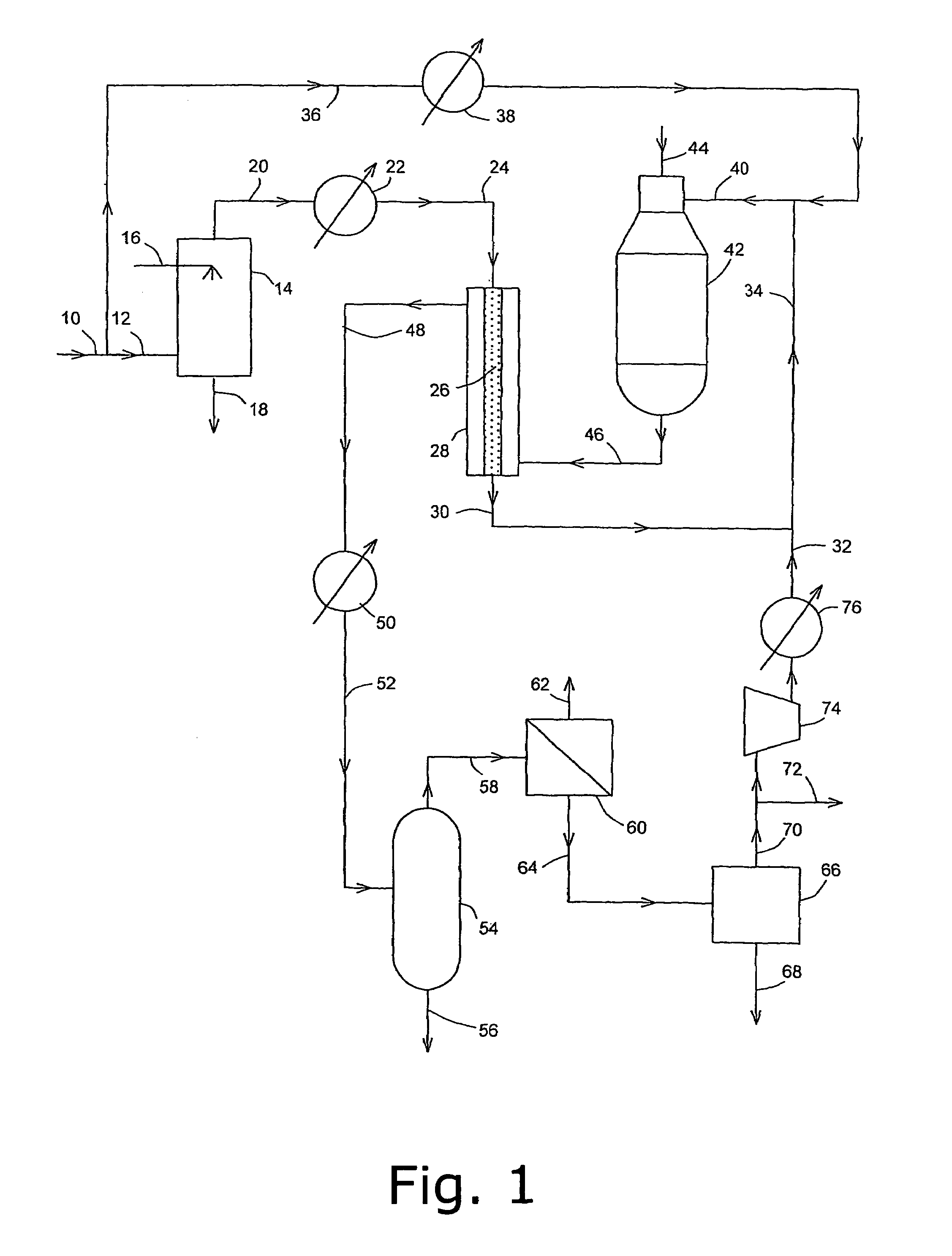
[0058]FIG. 4 is a table that contains data calculated for a Fischer-Tropsch process operated in accordance with the schematic depicted in FIG. 2. The data demonstrates that the process of the present invention is able to provide a steam ratio in the heat-exchange reactor tubes of 1.25 and thereby, with a nickel steam reforming catalyst avoid carbon deposition, yet based on total hydrocarbon feed to the process, the overall steam ratio is 1.0.

example 2

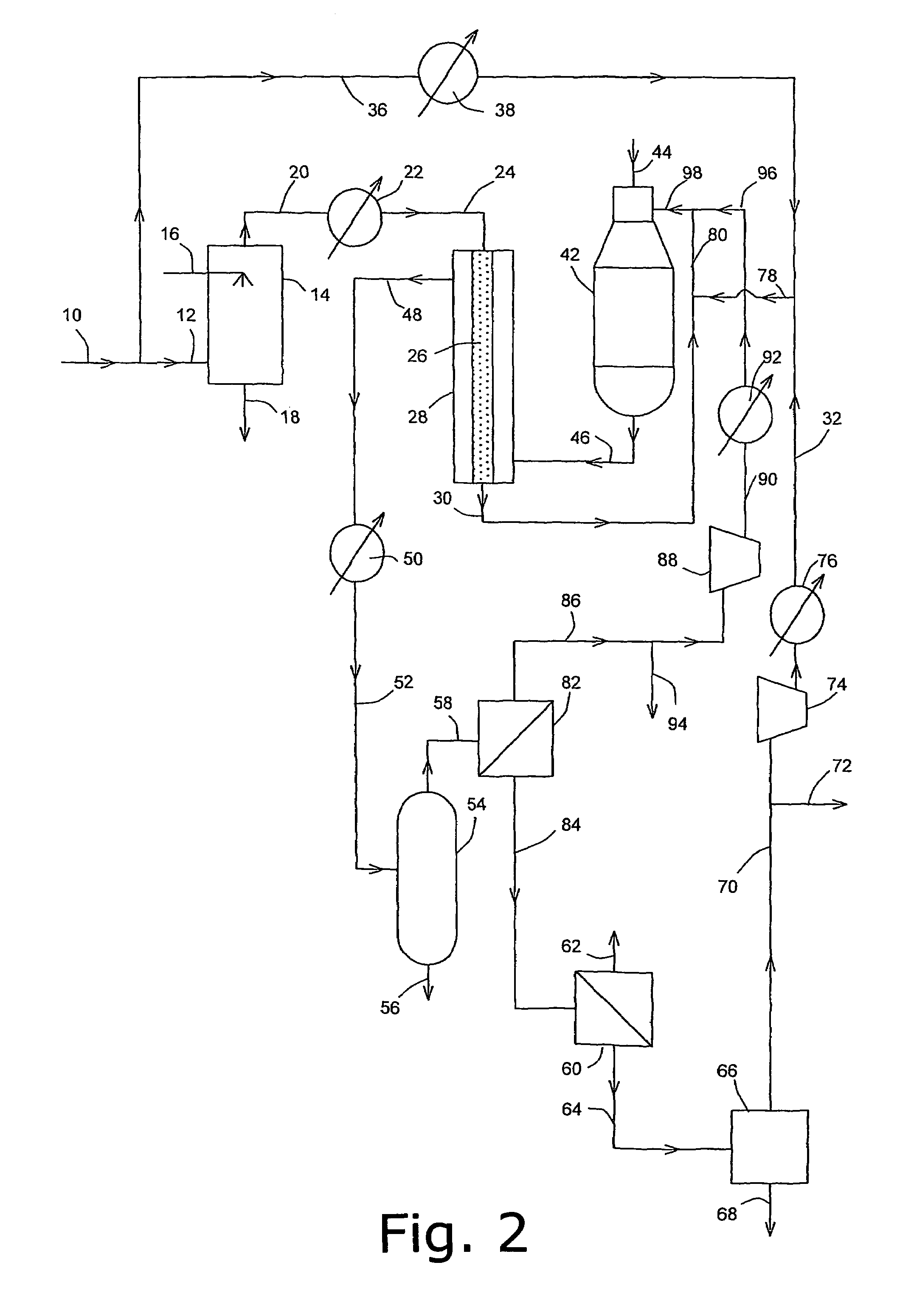
[0059]FIG. 5 is a table contains data calculated for a 80,000 barrel-per-day Fischer-Tropsch process operated in accordance with the schematic depicted in FIG. 3. The data demonstrated that the process of the present invention is able to provide a steam ratio in the heat-exchange reactor tubes of 0.88 and thereby, with a precious metal reforming catalyst avoid carbon deposition, yet based on total hydrocarbon fed to the process, the overall steam ratio is 0.66.

[0060]In the following table the pressure(P, in bar abs.), temperatures (T, in °C.) and flow rates (kmol / h) of the various components of the streams are quoted, rounded to the nearest integer. 1 bara=10000 Pa or 100 kPa.


PUM

PropertyMeasurementUnit
Percent by volumeaaaaaaaaaa
Volumeaaaaaaaaaa

Abstract

A process for production of hydrocarbons including a) reforming a divided hydrocarbon feedstock stream, mixing the first stream with steam, passing the mixture over a catalyst disposed in heated heat exchange reformer tubes to form a primary reformed gas, forming a secondary reformer feed stream including the primary reformed gas and the second hydrocarbon stream, partially combusting the secondary reformer feed stream and bringing the partially combusted gas towards equilibrium over a secondary catalyst, and producing a partially cooled reformed gas, b) further cooling the partially cooled reformed gas below the dew point of steam therein to condense water and separating condensed water to give a de-watered synthesis gas, c) synthesising hydrocarbons from the de-watered synthesis gas by the Fischer-Tropsch reaction and separating some of the synthesised hydrocarbons into a tail gas, and d) incorporating part of the tail gas into the secondary reformer feed stream before partial combustion thereof.

Description

[0001]This application is the U.S. national phase application of PCT International Application No. PCT / GB2003 / 004622, filed Oct. 23, 2003, and claims priority of British Patent Application No. 0225961.2, filed Nov. 7, 2002.FIELD OF THE INVENTION[0002]This invention relates to the production of hydrocarbons by the Fischer-Tropsch process and to the production of synthesis gas therefor. The synthesis gas contains hydrogen and carbon oxides and is produced by the catalytic reaction of steam with a hydrocarbon feedstock in a process known as steam reforming.BACKGROUND OF THE INVENTION[0003]Steam reforming is widely practised and is used to produce hydrogen streams and synthesis gas for a number of processes such as ammonia, methanol as well as the Fischer-Tropsch process. In a steam reforming process, a desulphurised hydrocarbon feedstock, e.g. methane, natural gas or naphtha, is mixed with steam and passed at elevated temperature and pressure over a suitable catalyst, generally a trans...

Claims


Application Information

Patent Timeline
IPC IPC(8): C07C27/00C01B3/38C10G2/00
CPCC01B3/382C01B3/384C10G2/32C01B2203/0233C01B2203/0244C01B2203/062C01B2203/0844C01B2203/1052C01B2203/12C01B2203/1241C01B2203/1247C01B2203/143C01B2203/146C01B2203/147C01B2203/148C01B2203/82
Inventor ABBOTT, PETER EDWARD JAMESFOWLES, MARTIN
Owner JOHNSON MATTHEY PLC
Learn More