Half-bridge driver and power conversion system with such driver

a technology of driver and power stage, which is applied in the direction of ac-dc conversion, logic circuit, push automatic control, etc., can solve the problems of dv/dt induced current in the current path of the set and reset node, dv/dt common mode induced current, and shoot-through in the power stage, so as to achieve reliable operation conditions

Inactive Publication Date: 2008-01-29
BANG & OLUFSEN ICEPOWER
View PDF7 Cites 27 Cited by
  • Summary
  • Abstract
  • Description
  • Claims
  • Application Information

AI Technical Summary

Benefits of technology

[0011]An object of the present invention is to provide a novel system for receiving and handling the set and reset current pulses in a high side driver, thereby obtaining reliable operating conditions for operating the power switching transistors.
[0015]According to the invention, the pulse generated signals stay as currents that are insensitive to capacitances, and also the driver is immune to negative offset voltages. Further, it is now possible to reduce the required drive voltage, thereby reducing power consumption and operating temperatures for the half-bridge driver.
[0016]The low impedance inputs result in elimination of voltage swings on the inputs and the dc bias point of these inputs will be as close as possible to the positive power supply of the high side driver. This will enable the level shift to show secure function even for high negative offset voltages because the decision points is no longer based on voltage drops across the prior pull up resistors. This feature is of great benefit in terms of power reduction, because it enables lowering of the operating voltage of the driver. This enables reduction of power dissipation, a reduction of the die size and an increase in the speed performance.

Problems solved by technology

In pulse control a major problem is common mode dv / dt induced currents in the current paths of the set and reset nodes, arising from parasitic capacities in current pulse generators.
The dv / dt at the output terminal (offset voltage) of the output stage can reach very high levels—thus even very small parasitic capacitances will result in dv / dt common mode induced currents.
The common mode noise can cause false operation of the output switch, resulting in shoot-through in the power stage.
This approach does not in it self provide any common mode rejection and additionally circuits have been mandatory.
Unfortunately this approach compromises speed and power efficiency because of the low pass filtering, which calls for an increase of the width of the current pulses.
Another approach has been to add logic circuitry after said pull up resistors to suppress common mode signals; this however involves a substantial amount of gate circuitry.
Therefore level shift circuits based on pull up resistors are challenged when the load terminal is negative with respect to ground.
This is caused by the fact that the voltage drops over the pull up resistors are limited which can course false operation of the MOSFET's.
In general, the use of pull up resistors is not suitable for logic level driver voltage because of the negative load terminal voltage that must be expected to compromise the logic level of the high side set / reset inputs.

Method used


Image

  • Half-bridge driver and power conversion system with such driver
  • Half-bridge driver and power conversion system with such driver
  • Half-bridge driver and power conversion system with such driver

Examples


Embodiment Construction

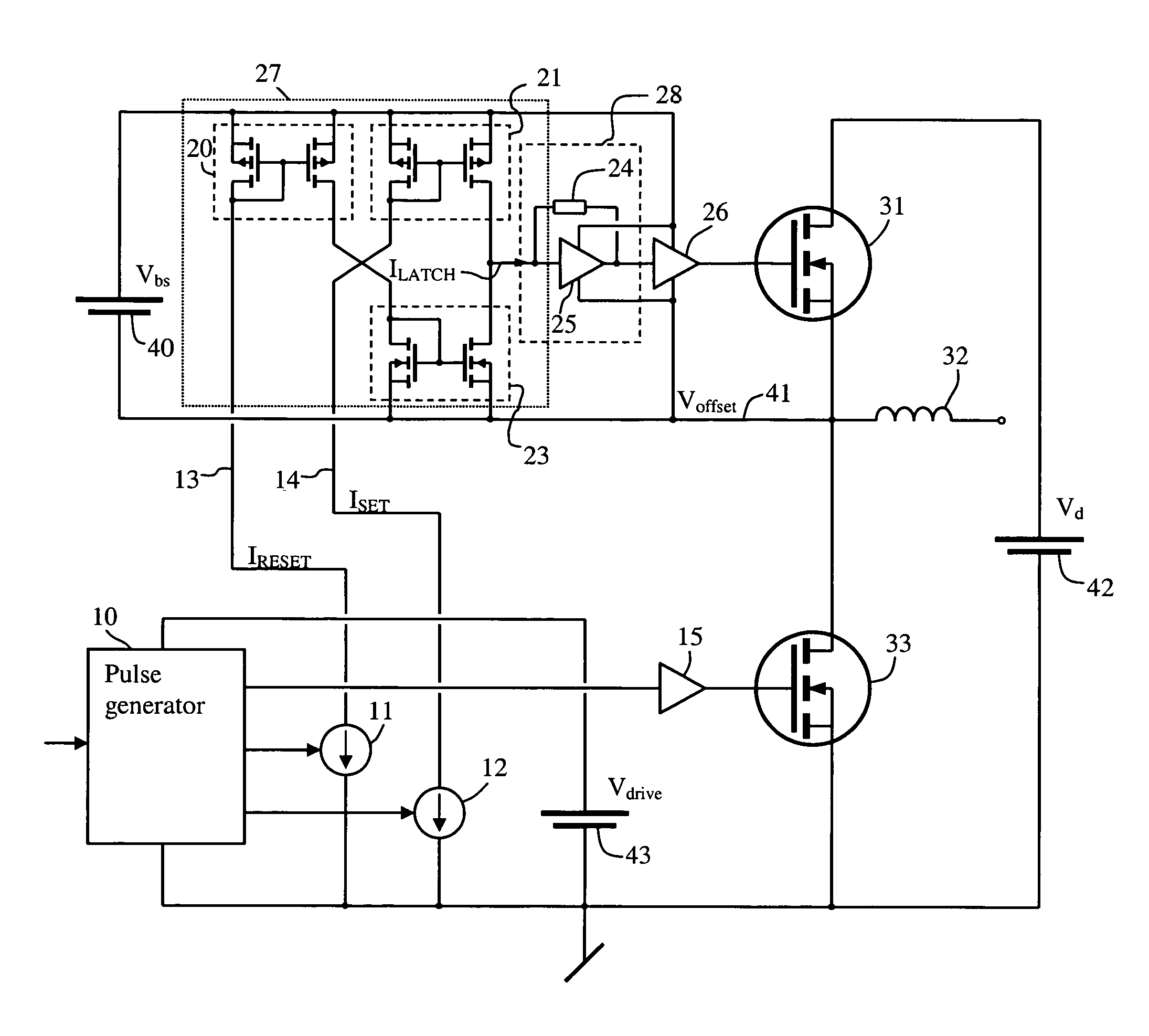
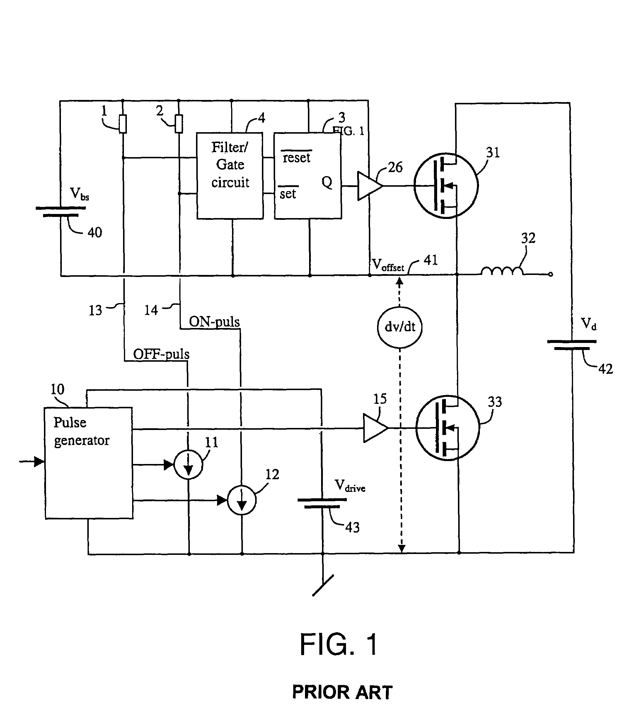
[0023]A topology for an output stage is illustrated in FIG. 1. The driver has two pull-up resistors 1, 2, a filter or gate block 4 for noise rejection, and a latch 3. The system further comprises current generators 11, 12 controlled by a pulse generator 10.

[0024]The output stage comprises two N-channel power switches 31 and 33. The load terminal is referred to as Voffset 41. The output terminals, 41 and ground or −Vd, can drive any type of load, for example an inductive load such as a coil or an electro-dynamic transducer. The offset voltage is also the reference potential for the high-side driver and will under normal operation be 0V or ±Vd 42. The high side driver is powered from the supply Vbs 40 and this voltage preferably equals the supply Vd 42.

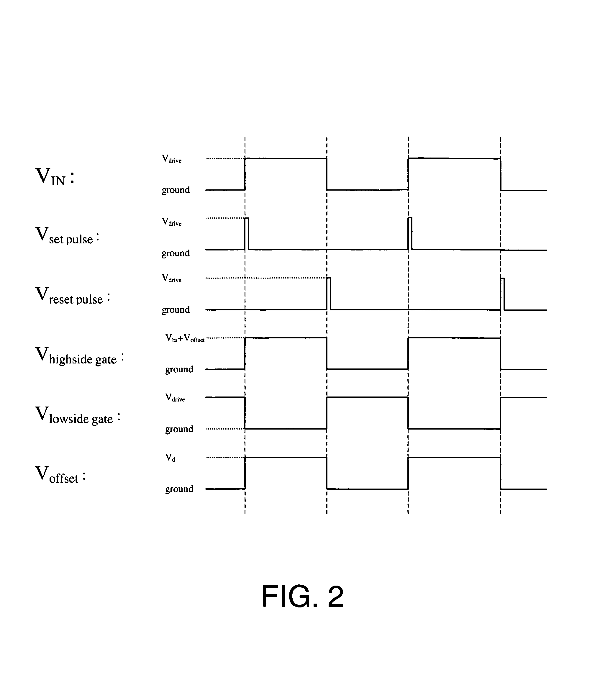
[0025]The basic functionality of the known prior art pulse controlled high side driver shown in FIG. 1 is explained in FIG. 2, showing the timing of the system. The current generators 11, 12 generate narrow current pulses at the rising ...


PUM


Abstract

A half-bridge driver includes first and second power switches, connected with their respective current paths in series, a pulse generator for generating a voltage pulse waveform, arranged to drive the first power switch, a first current generator for generating a current pulse for each negative flank of the voltage pulse waveform, a second current generator for generating a current pulse for each positive flank of said voltage pulse waveform, and a differential current receiver circuit. The differential current receiver circuit is connected to the first and second current generators, and is arranged to generate an output signal equal to the difference of the currents flowing through the current generators. The output signal is arranged to drive the second power switch.

Description

TECHNICAL FIELD[0001]The present invention relates to a half-bridge power stage driver, comprising first and second power switches, connected with their respective current paths in series, a pulse generator for generating a voltage pulse waveform, arranged to drive said first power switch, a first current generator, for generating a current pulse for each trailing edge of said voltage pulse waveform, and a second current generator, for generating a current pulse for each leading edge of said voltage pulse waveform.[0002]The invention can advantageously be used in power conversion systems where high-speed operation combined with low power consumption is required as e.g. motor drive and in particular in power amplification for audio use.TECHNICAL BACKGROUND[0003]A half-bridge is a power converter comprising two power switches, e.g. transistors, one referred to as the low side transistor, and the other referred to as the high side transistor. Each transistor is driven by separate drive...

Claims


Application Information

Patent Timeline
Patent Type & Authority Patents(United States)
IPC IPC(8): H03K3/02H03K3/36H02M1/08H03K17/06H03K17/687
CPCH03K17/063H03K17/6871H03K5/1252
Inventor NIELSEN, OLE NEIS
Owner BANG & OLUFSEN ICEPOWER
Why Eureka
Try Eureka