Single-stage buck-boost inverter

a technology of buck-boost power inverters and single-stage buck-boost, which is applied in the direction of ac network voltage adjustment, automatic controllers, electric variable regulation, etc., can solve the problems of nuclear waste disposal, nuclear waste disposal remains a serious issue, and new power generation capacity cannot be met by traditional methods such as burning coal, oil, natural gas,

Inactive Publication Date: 2008-02-19
UNIVERSITY OF NEW BRUNSWICK
View PDF6 Cites 50 Cited by
  • Summary
  • Abstract
  • Description
  • Claims
  • Application Information

AI Technical Summary

Benefits of technology

[0012]The simple circuit topology of the present invention provides the possibility for a low cost and high efficiency power converter. The inverter has a low component count with only four power switches, four diodes, and a compact high frequency transformer. Compared to traditional buck inverters with line-frequency transformers, two-stage buck-boost inverters, and many of single-stage buck-boost inverters, both the cost and size are reduced, thereby presenting a more reliable and more economic design in small DG systems. Two current control schemes, DCM and CCM, are presented with amplitude modulation techniques.

Problems solved by technology

As more countries ratify the Kyoto Accord, an international agreement to reduce greenhouse gas (GHG) emissions, new power generation capacity can no longer be met by traditional methods such as burning coal, oil, natural gas, etc.
Nuclear power plants have experienced safety problems and disposal of nuclear waste remains a serious issue.
Energy from the wind, sun, water, waves, tides, etc., is renewable and essentially inexhaustible but the output from such sources is widely dispersed and generally sporadic, fluctuating dramatically with the weather and the seasons.
Compared to two-stage buck-boost inverters, most of single-stage buck-boost inverters present a compact design with a good performance-cost ratio, but they suffer from low power capacity and limited operation range imposed to dc sources.
Some of them still have higher component count and more complicated operations, even compared with a two-stage inverter, and thus compromise their benefits.
Others limit their applications by either requiring split dc sources (FIG. 12) or imposing very high switching frequency (FIG. 13, FIG. 15) to demonstrate performance, or presenting low power ratings (FIG. 15).

Method used


Image

  • Single-stage buck-boost inverter
  • Single-stage buck-boost inverter
  • Single-stage buck-boost inverter

Examples


first embodiment

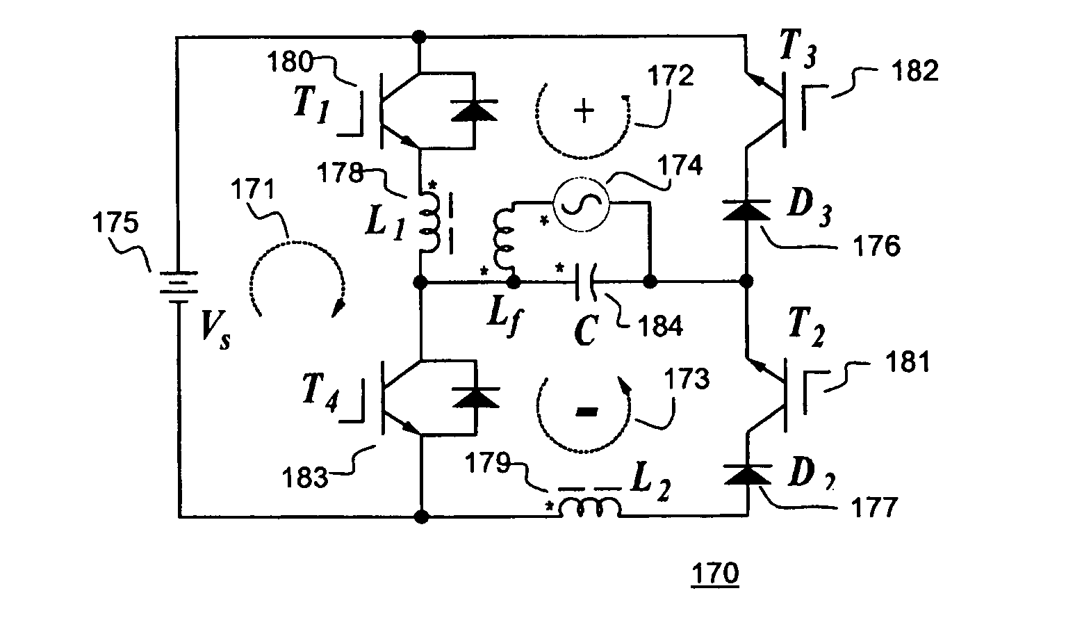
[0051]FIG. 17 is a schematic illustration of the S2B2 inverter 170 of the present invention. It consists of one charge loop 171 (T1 180, L1 178, and T4 183) and two discharge loops 172, 173 (T1 180, L1 178, C 184, D3 176, and T3 182 for the positive half cycle 172; and T4 183, L2 179, D2 177, T2 181, and C 184 for the negative half cycle 173). The reverse power flow from grid 174 to source Vs 175 is blocked by D3 176 and D2 177. The energy-storage components, L1 178 and L2 179, are the primary and secondary windings of a flyback transformer and have identical inductance (L) and number of turns. As is well understood in the art, the switches T1 180, T2 181, T3 182 and T4 183, are controlled by a separate control circuit not illustrated in FIG. 17.

[0052]Each of the functional loops 171, 172, 173 is associated with one of three switch operation modes. Charge loop 171 is used in charge mode, wherein switch T1 180 and T4 183 are on and switch T2 181 and T3 182 are off. An approximate equ...

second embodiment

[0067]the present invention is illustrated in FIG. 26. This single-stage buck-boost inverter 260 uses only three switching devices 261, 262, 263.

[0068]The circuit operation can be divided into four modes. Mode 1 and mode 2 work in positive half cycle, and mode 3 and mode 4 work in negative half cycle.

[0069]Positive half cycle: During mode 1, switching device Q1261 is turned on and switching devices Q2262 and Q3263 are turned off, the coupled inductor L1264 will be charged with input voltage 175; and during mode 2, switching device Q1261 and Q3263 are turned off and Q2262 is turned on, the energy in L1264 will be discharged to the grid through D2266.

[0070]Negative half cycle: During mode 3, switching device Q1261 is turned on again (Q2262 and Q3263 are turned off) and the coupled inductor L1264 will be charged; and during mode 4, switching device Q1261 and Q2262 will turned off and switching device Q3263 will turned on, the energy transferred to the coupled inductor L2265 from L1264,...


PUM

PropertyMeasurementUnit
peak currentaaaaaaaaaa
operating frequencyaaaaaaaaaa

Abstract

An improved Single-Stage Buck-Boost inverter (S2B2 Inverter) is provided, using only three or four power semiconductor switches and two coupled inductors in a flyback arrangement. The inverter can handle a wide range of dc input voltages and produce a fixed ac output voltage. The inverter is well suited to distributed power generation systems such as photovoltaic and wind power and fuel cells, for standalone or grid connected applications. The inverter has a single charge loop, a positive discharge loop and a negative discharge loop.

Description

CROSS-REFERENCE TO RELATED APPLICATIONS[0001]This application claims the benefit of U.S. provisional patent application 60 / 557,688, filed Mar. 31, 2004.MICROFICHE APPENDIX[0002]Not Applicable.TECHNICAL FIELD[0003]The present invention relates generally to power converters and more particularly to DC to AC buck-boost power inverters.BACKGROUND OF THE INVENTION[0004]Increasing global energy consumption and noticeable environmental pollution are making renewable energy more important. Today, a small percentage of total global energy comes from renewable sources, mainly hydro and wind power. However, global energy consumption is expected to expand by 58% between 2001 and 2025. As more countries ratify the Kyoto Accord, an international agreement to reduce greenhouse gas (GHG) emissions, new power generation capacity can no longer be met by traditional methods such as burning coal, oil, natural gas, etc. Also, these traditional sources are predicted to last only about 100 to 200 years in...

Claims


Application Information

Patent Timeline
Patent Type & Authority Patents(United States)
IPC IPC(8): H02M3/335G05B24/02H02J1/00G05F1/10H02M7/537
CPCH02M7/48Y02E10/56Y02E10/76
Inventor CHANG, LIUCHENLIU, ZHUOMIN
Owner UNIVERSITY OF NEW BRUNSWICK
Why Eureka
Try Eureka