Ultrasonic solution separator

a technology of ultrasonic solution and separator, which is applied in the direction of electrostatic separation, solid separation, combustible gas purification/modification, etc., can solve the problems of reducing the efficiency of atomization for producing and difficult to efficiently produce high-concentrated mist from a solution. , to achieve the effect of efficiently producing mist, efficiently separating a high-concentr

Active Publication Date: 2008-03-25
ULTRASOUND BREWERY
View PDF18 Cites 20 Cited by
  • Summary
  • Abstract
  • Description
  • Claims
  • Application Information

AI Technical Summary

Benefits of technology

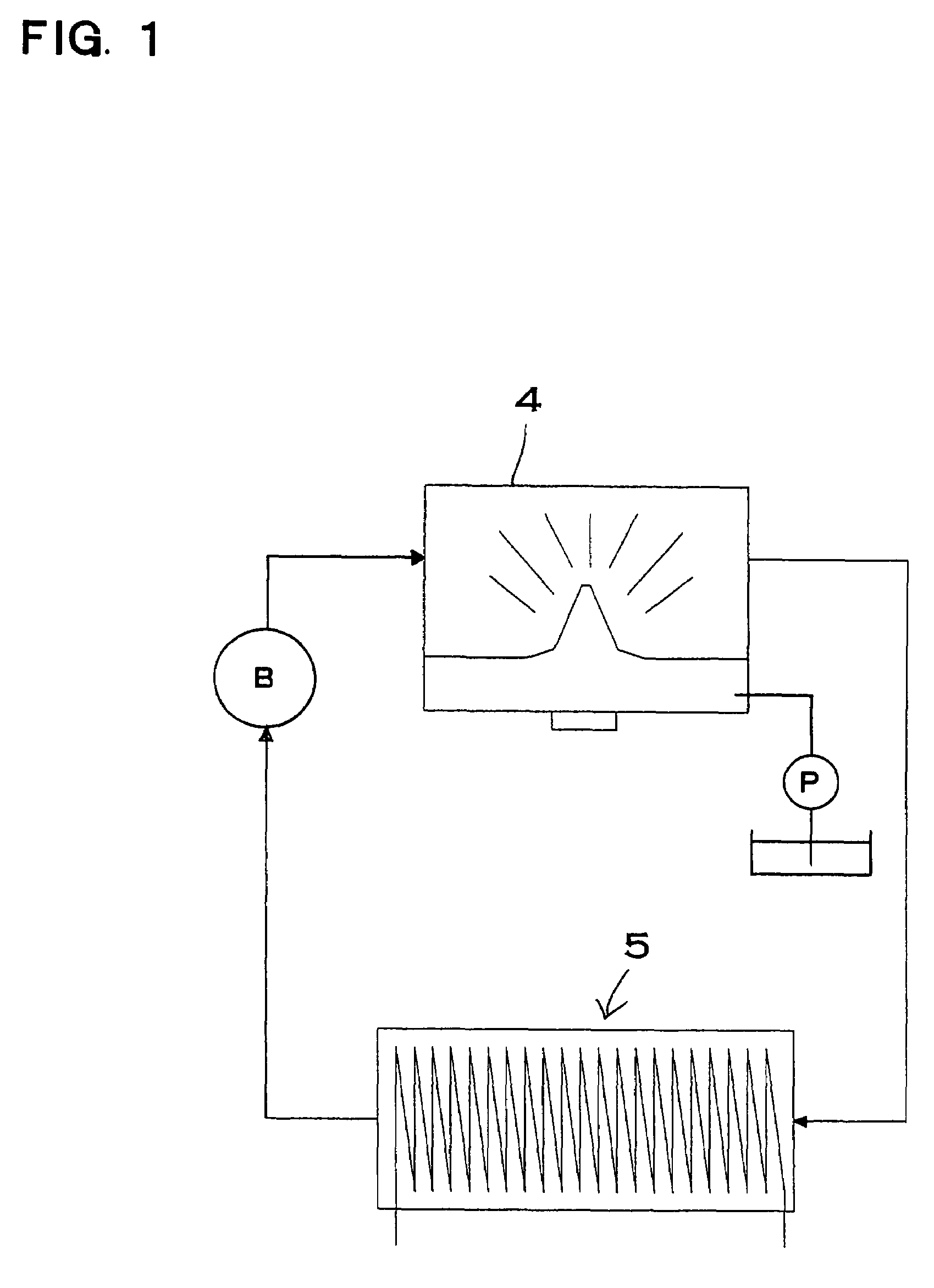
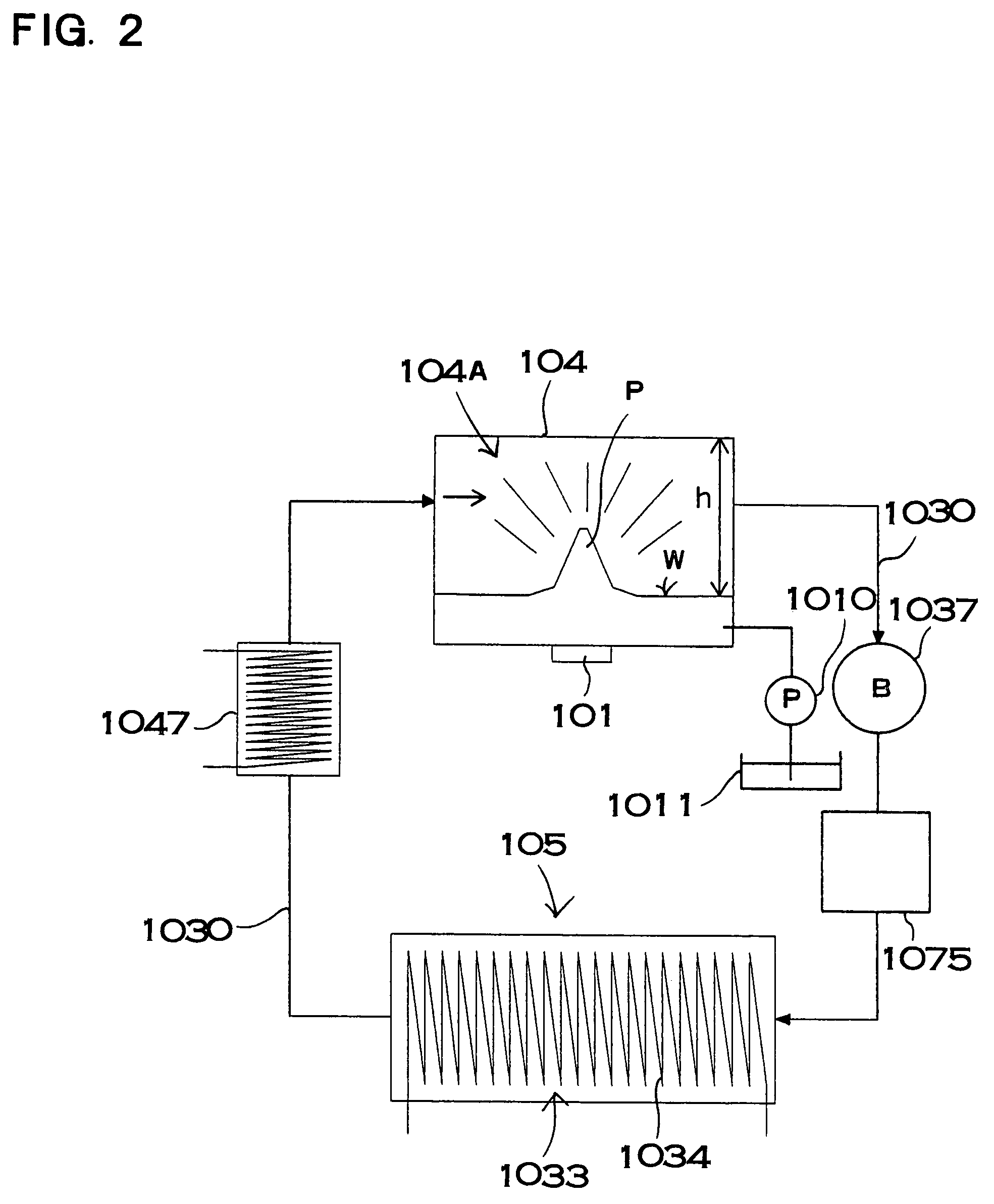
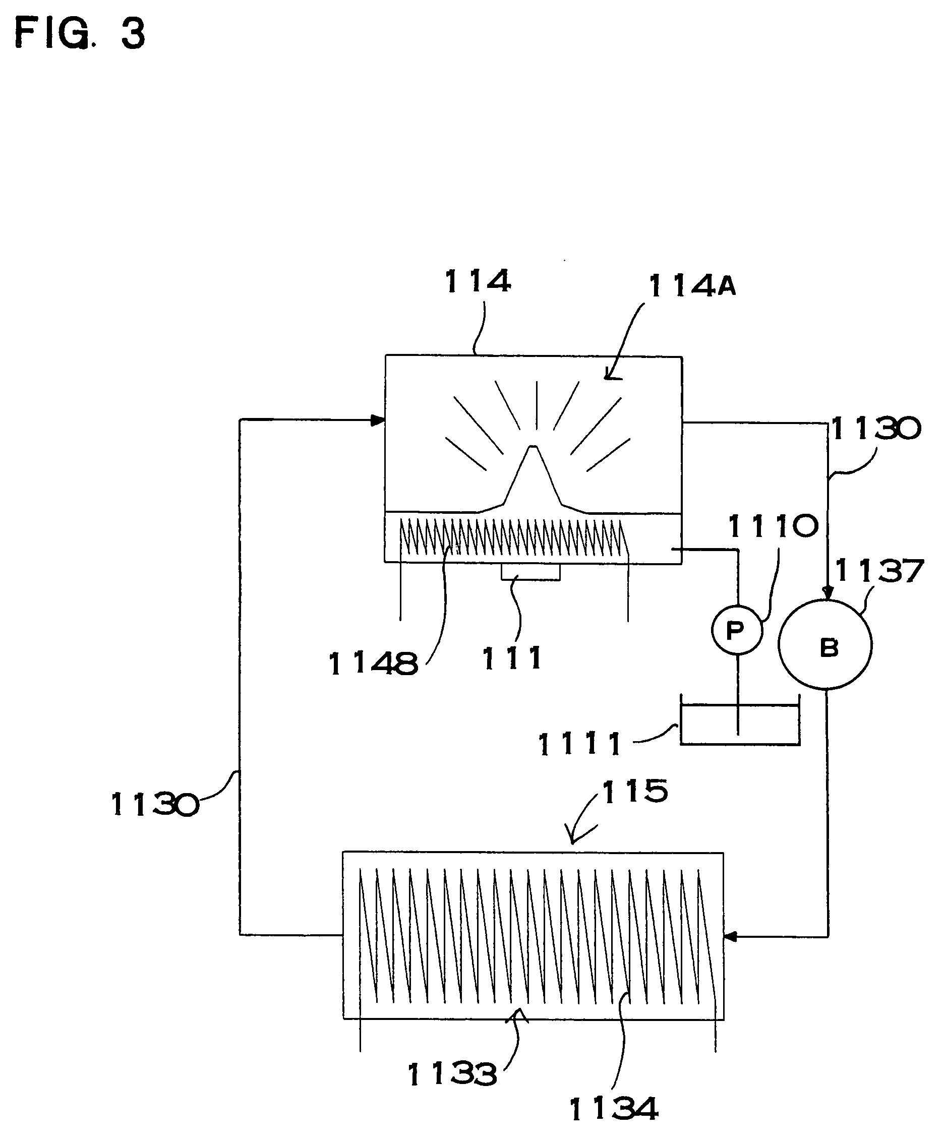
[0012]The above ultrasonic solution separator has an advantage that can efficiently produce mist from a solution in the ultrasonic atomization chamber, and additionally can collect the target material included in the mist produced from the solution whereby efficiently separating a high-concentrated solution. The reason is that the temperature of carrier gas in the ultrasonic atomization chamber is at least 5° C. higher than the carrier gas in the collection portion. A solution is oscillated at an ultrasonic frequency under this condition whereby producing mist, mist can be efficiently produced from the solution. The efficiency of mist production from a solution varies depending on the temperature of a carrier gas in contact with the surface of the solution. For this reason, when the temperature of a carrier gas is high, the efficiency of mist production is also high. A target material such as an alcohol and a solvent such as water vaporize from mist produced as fine liquid droplets. On the other hand, when the carrier gas is transported from the ultrasonic atomization chamber to the collection portion, the temperature of the carrier gas lowers at least 5°. When the temperature of the carrier gas lowers, the target material, which is included as vapor by the carrier gas, becomes supersaturated and condenses to a liquid. The condensate target material becomes droplets and is collected. Thus, the target material becomes mist in the ultrasonic atomization chamber, and then vaporizes from the mist, and finally becomes supersaturated and is collected in the collection portion. Therefore, the above ultrasonic solution separator has an advantage that efficiently produces mist from a solution, and, in addition, can efficiently also collect a target material whereby efficiently separating a high-concentrated solution.
[0038]Furthermore, in an ultrasonic solution separator according to another aspect of the present invention, a shield is provided for shielding the surface of the solution from a gas in the ultrasonic atomization chamber whereby preventing vaporization of the solution into the gas is provided on the surface of the solution. The shield is provided with a through hole, from which the liquid column protrudes, wherein an outlet is arranged to eject the solution provided on the upper surface of the shield whereby separating the solution provided on the upper surface of the shield from the solution of the ultrasonic atomization chamber.

Problems solved by technology

Accordingly, the apparatus has a disadvantage that the concentration of alcohol in a solution, which is obtained by collecting mist, reduces, though the mist with a high concentration of alcohol is produced by means of ultrasonic waves.
On the other hand, if the temperature of the carrier gas in the ultrasonic atomization chamber is low, the efficiency of atomization for producing mist from a solution is remarkably reduced.
In this case, it is difficult to efficiently produce high-concentrated mist from a solution.
In order to achieve this requirement, it is necessary to increase the performance of the ultrasonic oscillator and a power source for driving the ultrasonic oscillator, thus, both equipment costs and running costs should be high.
Such an apparatus is not economical.

Method used


Image

  • Ultrasonic solution separator
  • Ultrasonic solution separator
  • Ultrasonic solution separator

Examples


Embodiment Construction

[0075]An ultrasonic solution separator according to the present invention separates a target material, which quickly moves to its surface and exhibits the characteristics of surface excess, from a solution. Water is mainly used as a solvent, however, solutes and solvents are not specifically limited. For example, organic solvents such as an alcohol can be used other than water. The following solutions including target materials can be used, for example.

[0076](1) Sake, beer, wine, vinegar, mirin (rice cooking wine), spirits, shochu, brandy, whiskey and liqueur.

[0077](2) Solutions containing perfumes such as pinene, linalool, limonene and polyphenol group, and aromatic compounds or fragrant compounds.

[0078](3) Solutions containing alkane and cycloalkane, which are saturated hydrocarbon, alkene, cycloalken and alkyne, which are unsaturated hydrocarbon, any of organic compounds classed as a group of ether, thioether and aromatic hydrocarbon, or a compound consisting of bounded two or mo...


PUM

PropertyMeasurementUnit
temperatureaaaaaaaaaa
velocityaaaaaaaaaa
heightaaaaaaaaaa

Abstract

An ultrasonic solution separator including an ultrasonic atomization chamber supplied with a solution containing a target material; an ultrasonic oscillator producing mist from the solution in the ultrasonic atomization chamber with ultrasonic oscillation; a power supply for ultrasonics connected to the ultrasonic oscillator, and a collection portion transporting the mist produced by the ultrasonic oscillator with a carrier gas and aggregating and collecting the mist included in the carrier gas. The power supply supplying high-frequency power to the ultrasonic oscillator so that the ultrasonic oscillator oscillates at an ultrasonic frequency. The ultrasonic separator aggregates and collects the mist produced in the ultrasonic atomization chamber by means of the collection portion. With this ultrasonic solution separator, the temperature of carrier gas in the ultrasonic atomization chamber is at least 5° C. higher than the carrier gas in the collection portion.

Description

BACKGROUND OF THE INVENTION[0001]1. Technical Field[0002]The present invention relates to an alcohol separator which separates a higher concentration of alcohol from an alcohol solution of sake (Japanese rice wine), other alcoholic beverage raw material, or solution of volatile organic compounds.[0003]2. Description of Related Art[0004]The inventor has developed a separator which separates a target material with the characteristics of surface excess such as an alcohol by producing mist by means of ultrasonic waves (see Patent Document 1).[0005]Patent Document 1: Japanese Patent Laid-Open Publication TOKUKAI No. 2001-314724 With this type of alcohol separator, an alcohol solution is filled into an ultrasonic atomization chamber with a seal structure, and the alcohol solution in the ultrasonic atomization chamber is atomized into mist by means of ultrasonic oscillation of an ultrasonic oscillator. The alcohol separator aggregates and collects the atomized mist, and separates a higher ...

Claims


Application Information

Patent Timeline
Patent Type & Authority Patents(United States)
IPC IPC(8): B01D3/00B01D1/00B01D51/00B01D51/02C12G3/12B05B17/06B01F11/00B01F3/04B03C3/014B01D3/06B01D3/34B01D5/00B01D17/02C12H6/00C12H6/02
CPCB01D3/06B01D3/346B01D5/0027B01D5/0039B01D5/0042B01D5/0045B01D5/0081B01D5/0087B01D5/009B01D17/0205B05B17/0615B05B17/0646B01D17/04B01D17/042B01D17/048Y10S261/48
Inventor MATSUURA, KAZUOSATO, MASANORI
Owner ULTRASOUND BREWERY
Why Eureka
Try Eureka